Installation instructions
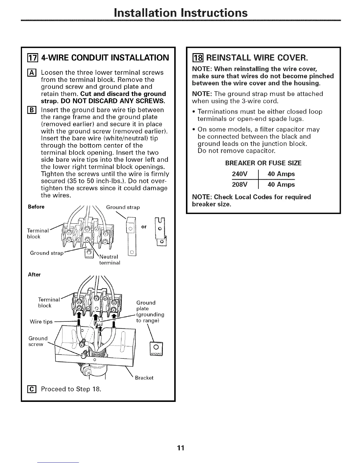
r_ 4-WIRE CONDUIT INSTALLATION
[]
[]
Loosen the three lower terminal screws
from the terminal block. Remove the
ground screw and ground plate and
retain them. Cut and discard the ground
strap. DO NOT DISCARD ANY SCREWS.
Insert the ground bare wire tip between
the range frame and the ground plate
(removed earlier) and secure it in place
with the ground screw (removed earlier).
Insert the bare wire (white/neutral) tip
through the bottom center of the
terminal block opening. Insert the two
side bare wire tips into the lower left and
the lower right terminal block openings.
Tighten the screws until the wire is firmly
secured (35 to 50 inch-lbs.). Do not over-
tighten the screws since it could damage
the wires.
Before
Terminal
block
Ground strap _
_ound strap
\Neutral
terminal
After
blTeorcr_inal _YA_',JLV:IJ_ re/ _1_)lll Ground
_.[,_I j,0_"_ I_ plate
W_'_ Etj_ _/t_J_---'_" (grounding
Wire tips -- =--------I, _.---" "_ to range)
oroun, \
screwrac
[] Proceed to Step 18.
[_] REINSTALL WIRE COVER.
NOTE: When reinstalling the wire cover,
make sure that wires do not become pinched
between the wire cover and the housing.
NOTE: The ground strap must be attached
when using the 3-wire cord.
• Terminations must be either closed loop
terminals or open-end spade lugs.
On some models, a filter capacitor may
be connected between the black and
ground leads on the junction block.
Do not remove capacitor.
BREAKER OR FUSE SIZE
240V 40 Amps
208V 40 Amps
NOTE: Check Local Codes for required
breaker size.
11
 Loading...