MA-041 – DGA 900 Plus - Installation & Commissioning Manual - Rev 1.1 4-Mar-22 Page 33 of 99
9 CARD OPTION #4: BUSHING & PD MONITOR
The Bushing & PD card:
▪ measures the condition of transformer bushings (through changes in Capacitance
and Power Factor) for one or two sets of three bushings in a single three-phase
transformer, or three single-phase transformers.
▪ detects any Partial Discharges (PD) activity in the transformer main tank (measured
as high frequency pulses).
This option uses the following adaptors and sensors:
▪ Three Bushing Adaptors (Primary input) connected to the tapping point of the
bushings being monitored.
▪ (Optional) Three Bushing Adaptors (Secondary input) connected to the tapping point
of a second set of bushings being monitored.
▪ Three High Frequency Current Transformer (HFCT) sensors at the transformer(s)
neutral (if applicable).
▪ Three magnetically-mounted temperature sensors (MMTS) mounted on the
transformer tank(s) to measure the transformer top oil temperature (if applicable).
All commissioning details are found in Section 10.4. Refer to the ‘MA-040 – DGA 900 Plus
– Operator Guide’ for all other operational details relating to the software interface for
configuration, bushing settings, data readings and alarms.
Note: A complete list of parts and tools required for the Bushing & PD monitor
installation is given in Appendix A.
9.1 Installation Layout
See Section 7 of the standard MA-024 DGA 900 Installation Manual for further guidance
on mounting and location advice.
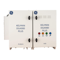
Figure 9-1 illustrates the general installation layout of a DGA 900 Plus with the required
connections for a single transformer.
 Loading...


