GE Multilin M60 Motor Protection System 6-23
6 ACTUAL VALUES 6.3 METERING
6
6.3.7 TRACKING FREQUENCY
PATH: ACTUAL VALUES METERING TRACKING FREQUENCY
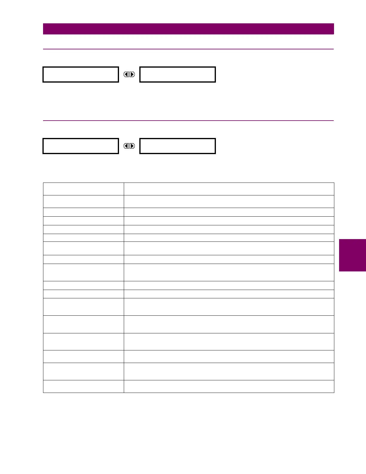
The tracking frequency is displayed here. The frequency is tracked based on the selection of the reference source with the
FREQUENCY AND PHASE REFERENCE setting in the SETTINGS SYSTEM SETUP POWER SYSTEM menu. See the Power
System section of chapter 5 for details.
6.3.8 FLEXELEMENTS
PATH: ACTUAL VALUES METERING FLEXELEMENTS FLEXELEMENT 1(16)
The operating signals for the FlexElements are displayed in pu values using the following definitions of the base units.
TRACKING FREQUENCY
TRACKING FREQUENCY:
60.00 Hz
FLEXELEMENT 1
FLEXELEMENT 1
OpSig: 0.000 pu
Table 6–2: FLEXELEMENT BASE UNITS
CURRENT UNBALANCE
(Amp Unbalance)
BASE = 100%
dcmA BASE = maximum value of the
DCMA INPUT MAX setting for the two transducers configured
under the +IN and –IN inputs.
FREQUENCY f
BASE
= 1 Hz
PHASE ANGLE
BASE
= 360 degrees (see the UR angle referencing convention)
POWER FACTOR PF
BASE
= 1.00
RTDs BASE = 100°C
SENSITIVE DIR POWER
(Sns Dir Power)
P
BASE
= maximum value of 3 V
BASE
I
BASE
for the +IN and –IN inputs of the sources
configured for the sensitive power directional element(s).
SOURCE CURRENT I
BASE
= maximum nominal primary RMS value of the +IN and –IN inputs
SOURCE ENERGY
(Positive and Negative Watthours,
Positive and Negative Varhours)
E
BASE
= 10000 MWh or MVAh, respectively
SOURCE POWER P
BASE
= maximum value of V
BASE
I
BASE
for the +IN and –IN inputs
SOURCE VOLTAGE V
BASE
= maximum nominal primary RMS value of the +IN and –IN inputs
STATOR DIFFERENTIAL
CURRENT
(Stator Diff Iar, Ibr, and Icr)
I
BASE
= maximum primary RMS value of the +IN and –IN inputs
(CT primary for source currents, and bus reference primary current for bus differential currents)
STATOR RESTRAINING
CURRENT
(Stator Diff Iad, Ibd, and Icd)
I
BASE
= maximum primary RMS value of the +IN and –IN inputs
(CT primary for source currents, and bus reference primary current for bus differential currents)
THERMAL MODEL
(Model Capacity Used)
(Model Motor Unbalance)
BASE =100%
THERMAL MODEL
(Model Lockout Time)
BASE = 10 minutes
THERMAL MODEL
(Thermal Model Load)
(Biased Motor Load)
BASE = 1.00 pu of FLA
THERMAL MODEL
(Trip Time on Overload)
BASE = 10 seconds

 Loading...


