GE Multilin M60 Motor Protection System 3-37
3 HARDWARE 3.3 DIRECT INPUT/OUTPUT COMMUNICATIONS
3
3.3.9 C37.94SM INTERFACE
The UR-series C37.94SM communication modules (2A and 2B) are designed to interface with modified IEEE C37.94 com-
pliant digital multiplexers or IEEE C37.94 compliant interface converters that have been converted from 820 nm multi-mode
fiber optics to 1300 nm ELED single-mode fiber optics. The IEEE C37.94 standard defines a point-to-point optical link for
synchronous data between a multiplexer and a teleprotection device. This data is typically 64 kbps, but the standard pro-
vides for speeds up to 64n kbps, where n = 1, 2,…, 12. The UR-series C37.94SM communication module is 64 kbps only
with n fixed at 1. The frame is a valid International Telecommunications Union (ITU-T) recommended G.704 pattern from
the standpoint of framing and data rate. The frame is 256 bits and is repeated at a frame rate of 8000 Hz, with a resultant bit
rate of 2048 kbps.
The specifications for the module are as follows:
• Emulated IEEE standard: emulates C37.94 for 1 64 kbps optical fiber interface (modules set to n = 1 or 64 kbps)
• Fiber optic cable type: 9/125 m core diameter optical fiber
• Fiber optic mode: single-mode, ELED compatible with HP HFBR-1315T transmitter and HP HFBR-2316T receiver
• Fiber optic cable length: up to 11.4 km
• Fiber optic connector: type ST
• Wavelength: 1300 ±40 nm
• Connection: as per all fiber optic connections, a Tx to Rx connection is required
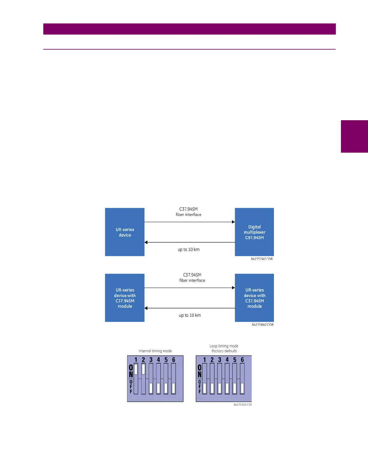
The UR-series C37.94SM communication module can be connected directly to any compliant digital multiplexer that sup-
ports C37.94SM as shown below.
It can also can be connected directly to any other UR-series relay with a C37.94SM module as shown below.
The UR-series C37.94SM communication module has six switches that are used to set the clock configuration. The func-
tions of these control switches are shown below.
For the internal timing mode, the system clock is generated internally. Therefore, the timing switch selection should be
internal timing for relay 1 and loop timed for relay 2. There must be only one timing source configured.

 Loading...


