GE Multilin M60 Motor Protection System 5-77
5 SETTINGS 5.2 PRODUCT SETUP
5
All major self-test alarms are reported automatically with their corresponding FlexLogic operands, events, and targets. Most
of the minor alarms can be disabled if desired.
When in the Disabled mode, minor alarms do not assert a FlexLogic operand, write to the event recorder, or display target
messages. Moreover, they do not trigger the
ANY MINOR ALARM or ANY SELF-TEST messages. When in Enabled mode,
minor alarms continue to function along with other major and minor alarms. See the Relay Self-tests section in chapter 7 for
information on major and minor self-test alarms.
5.2.12 CONTROL PUSHBUTTONS
PATH: SETTINGS PRODUCT SETUP CONTROL PUSHBUTTONS CONTROL PUSHBUTTON 1(7)
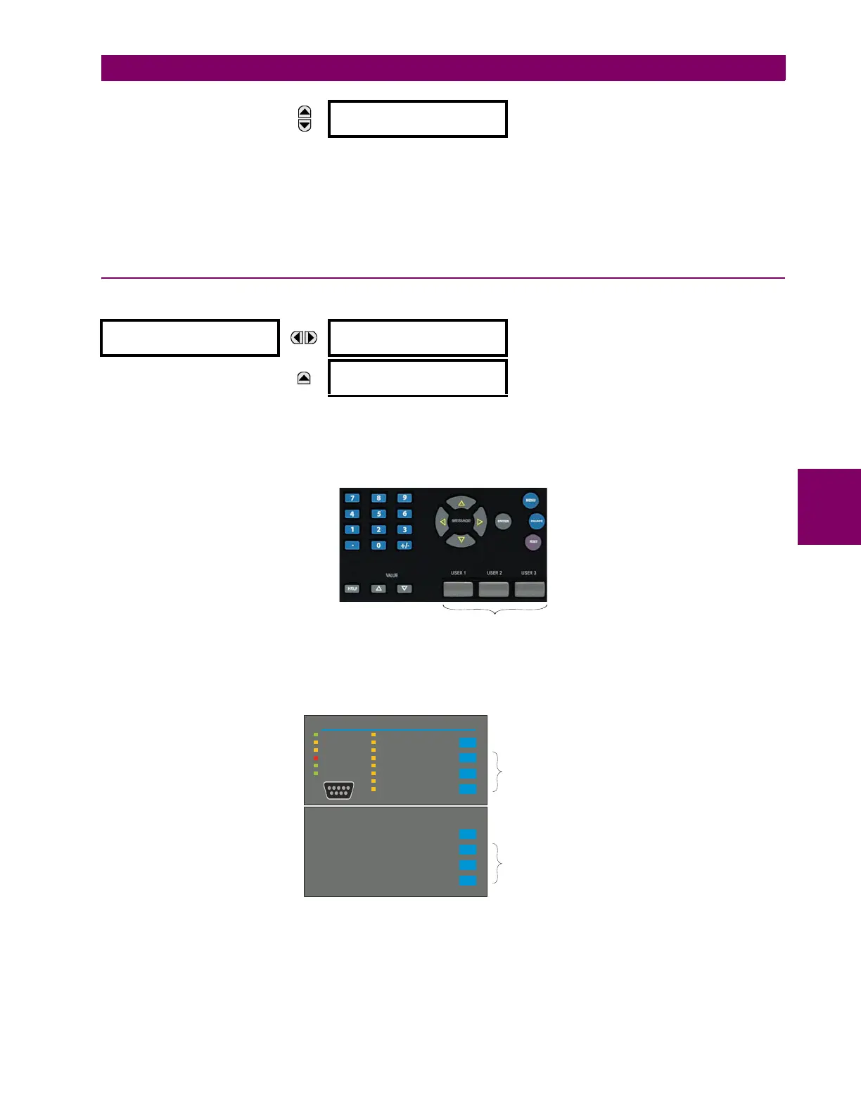
There are three standard control pushbuttons, labeled USER 1, USER 2, and USER 3, on the standard and enhanced front
panels. These are user-programmable and can be used for various applications such as performing an LED test, switching
setting groups, and invoking and scrolling though user-programmable displays.
The location of the control pushbuttons are shown in the following figures.
Figure 5–11: CONTROL PUSHBUTTONS (ENHANCED FACEPLATE)
An additional four control pushbuttons are included on the standard faceplate when the M60 is ordered with the 12 user-
programmable pushbutton option.
Figure 5–12: CONTROL PUSHBUTTONS (STANDARD FACEPLATE)
Control pushbuttons are not typically used for critical operations and are not protected by the control password. However,
by supervising their output operands, the user can dynamically enable or disable control pushbuttons for security reasons.
MESSAGE
SFP MODULE FAIL
FUNCTION: Disabled
Range: Disabled, Enabled.
CONTROL
PUSHBUTTON 1
CONTROL PUSHBUTTON 1
FUNCTION: Disabled
Range: Disabled, Enabled
MESSAGE
CONTROL PUSHBUTTON 1
EVENTS: Disabled
Range: Disabled, Enabled
Control pushbuttons
842813A1.CDR
842733A2.CDR
PICKUP
ALARM
TRIP
TEST MODE
TROUBLE
IN SERVICE
STATUS
USER 3
USER 2
USER 1
RESET
EVENT CAUSE
NEUTRAL/GROUND
PHASE C
PHASE B
PHASE A
OTHER
FREQUENCY
CURRENT
VOLTAGE
THREE
STANDARD
CONTROL
PUSHBUTTONS
USER 7
USER 6
USER 5
USER 4
FOUR EXTRA
OPTIONAL
CONTROL
PUSHBUTTONS

 Loading...


