4.2 VOLTAGE DEPENDENT OVERCURRENT LOGIC
V Dep OC V<2 Set
V Dep OC V<1 Set
V Dep OC V<1 Set
V Dep OC V<1 Set
V Dep OC k Set
I>1 Current Set
I>1 Current Set
Vdep OC Start AB
V Dep OC V<2 Set
I>1 Current Set
V Dep OC k Set
I>1 Current Set
Functional
Operator
1
V Dep OC Status
VRO I>1
VCO I>1
&
&
&
1
&
V Dep OC k Set
V00644
&
×
×
Applied Current
Threshold
Note : This diagram does not show all stages . Other stages follow
similar principles.
VAB
VAB
VAB
VAB
VAB
VAB
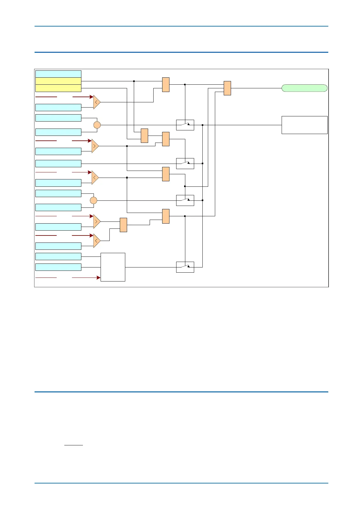
Figure 40: Voltage dependant overcurrent logic (Phase A to phase B)
The curr
ent thr
eshold setting for the Overcurrent function is determined by the voltage.
If the voltage is greater than V Dep OC V<1 Set, the normal overcurrent setting I>1 current set is used. this applies
to both VCO and VRO modes.
If the voltage is less than V Dep OC V<1 Set AND it is in VCO mode, the overcurrent setting I>1 current set is
multiplied by the factor set by V Dep OC k set.
If the voltage is less than V Dep OC V<2 Set AND it is in VRO mode, the overcurrent setting I>1 current set is
multiplied by the factor set by V Dep OC k set.
If the voltage is between V Dep OC V<1 Set and V Dep OC V<2 Set AND it is in VRO mode, the overcurrent setting is
multiplied by a functional operator to determine the setting.
4.3 APPLICATION NOTES
4.3.1 SETTING GUIDELINES
The V Dep OC k setting should be set low enough to allow operation for r
emote phase-to-phase faults, typically:
P14x Chapter 6 - Current Protection Functions
P14xEd1-TM-EN-1 107
 Loading...


