V00671
R
Z
m1
R
C
T1
R
L1
Z
m2
V
s
R
CT2
R
L3
I
F
I
S
R
L4
R
L2
Healthy CT
Saturated CT
A-G
Protected
circuit
I
R
ST
I = I
s
+ I
F
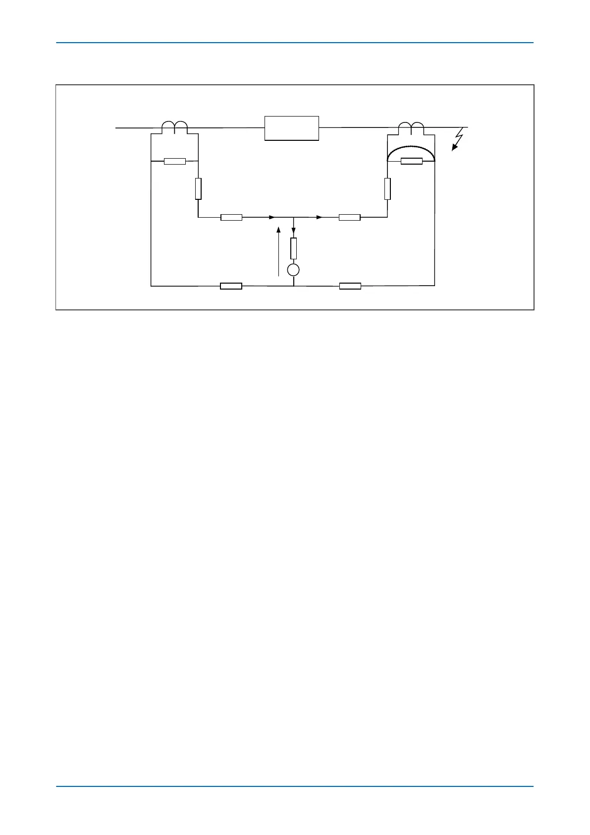
Figure 92: High Impedance REF principle
When subjected to heavy through faults the line curr
ent transformer may enter saturation unevenly, resulting in
imbalance. To ensure stability under these conditions a series connected external resistor is required, so that most
of the unbalanced current will flow through the saturated CT. As a result, the current flowing through the device
will be less than the setting, therefore maintaining stability during external faults.
Voltage across REF element V
s
= I
F
(R
CT2
+ R
L3
+ R
L4
)
Stabilising resistor R
ST
= V
s
/I
s
–R
R
where:
● I
F
= maximum secondary through fault current
● R
R
= device burden
● R
CT
= CT secondary winding resistance
● R
L2
and R
L3
= Resistances of leads from the device to the current transformer
● R
ST
= Stabilising resistor
High Impedance REF can be used for either delta windings or star windings in both solidly grounded and
resistance grounded systems. The connection to a modern IED are as follows:
P14x Chapter 7 - Restricted Earth Fault Protection
P14xEd1-TM-EN-1 169
 Loading...


