V00632
I
A1
I
B1
I
R1
-jX
C1
I
H1
I
A2
I
B2
I
R2
I
L
-jX
C2
jXL
I
H 2
I
A3
IB3
IC3 = IF
-jX
C3
I
R3
I
F
IH3
I
H1
+ I
H2
I
L
= I
F
+ I
H1
+ I
H2
+ I
H3
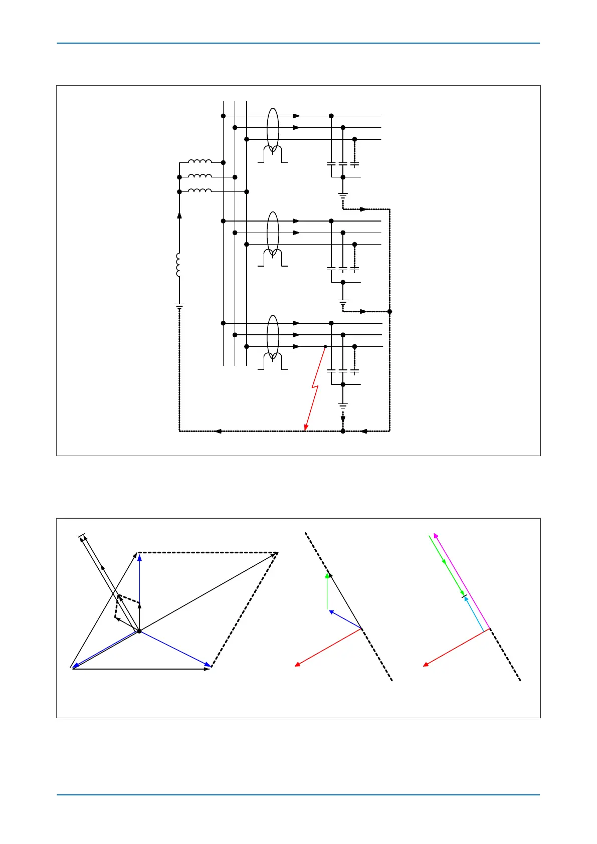
Figure 54: Distribution of currents during a Phase C fault
Assuming that no resistance is pr
esent in X
L
or X
C
, the resulting phasor diagrams will be as shown in the figure
below:
V00633
V
res
= -3V
o
I
R1
= I
H1
I
a1
I
b1
V
res
= -3V
o
I
R3
= I
F
+ I
H3
I
L
-I
H1
-I
H2
I
R3
= I
L
- I
H1
- I
H2
a) Capacitive and inductive currents
C B
A 3V0
I
H3
I
H2
IL
I
H1
I
B1
IA1
N
b) Unfaulted line c) Faulted line
Figure 55: Phasors for a phase C earth fault in a Petersen Coil earthed system
Chapter 6 - Current Protection Functions P14x
126 P14xEd1-TM-EN-1
 Loading...


