CHAPTER 2: INSTALLATION ELECTRICAL INSTALLATION
MM200 MOTOR MANAGEMENT SYSTEM – INSTRUCTION MANUAL 2–17
Contact inputs can be programmed to any of the input functions, such as field stop. The
exception is that contactor A status is fixed as the first contact input, and contactor B
status (where used) is fixed as the second contact input.
The three contact outputs can be programmed to follow any one of the digital signals
developed by the MM200, such as alarms and status signals. The exception is that the
contactor A relay is fixed as the first contact output, and contactor B relay is fixed as the
second contact output (where used).
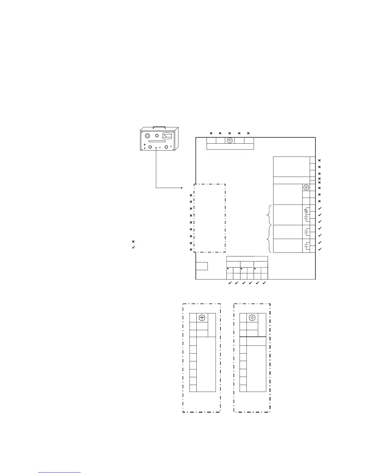
Dielectric strength testing
Figure 2-21: Testing for dielectric strength
Figure 2-22: LO and HI inputs
Do not HI-POT test
HI-POT test at 1.9 kV AC for 1 second, or
1.6 kV AC for 1 minute (per UL 508)
LINE FAULT
ON
POWER
FAULT
RESET
kV
VOLTAGE ADJUST
HV ON
DIELECTRIC STRENGTH TESTER
BLACK RED
888738A2.CDR
C1
C2
C4
C3
C5
C6
MM200
Motor Management System
C8
C9
C10
C7
Two form-A
contact outputs
CONTACT OUTPUT 2
One form-C
contact output
CONTACT OUTPUT 1
CONTACT OUTPUT 3
THERMISTOR
CBCT
RS485
R
I
-
+
-
+
C
B3
B4
B5
B6
B7
B8
I
R
I
R
I
R
CT1
CT2
CT3
CT MODULE
RJ45
PROFIBUS OR DEVICENET
V-
L
H
V+
A10
LO and HI
inputs
- see below -
A1
A2
A4
A3
A5
A6
A8
A9
A10
A7
+
-
24 VDC CONTACT INPUTS
CONTROL
POWER (VDC)
A1
A2
A4
A3
A5
A6
A8
A9
A10
L
N
VAC CONTACT INPUT
S
CONTROL
POWER (VAC)
NR
LO
HI
888742B1.cdr
RETURN