CHAPTER 2: INSTALLATION MECHANICAL INSTALLATION
MM200 MOTOR MANAGEMENT SYSTEM – INSTRUCTION MANUAL 2–3
Mounting
CAUTION:
To avoid the potential for personal injury due to fire hazards, ensure the unit is
mounted in a safe location and/or within an appropriate enclosure.
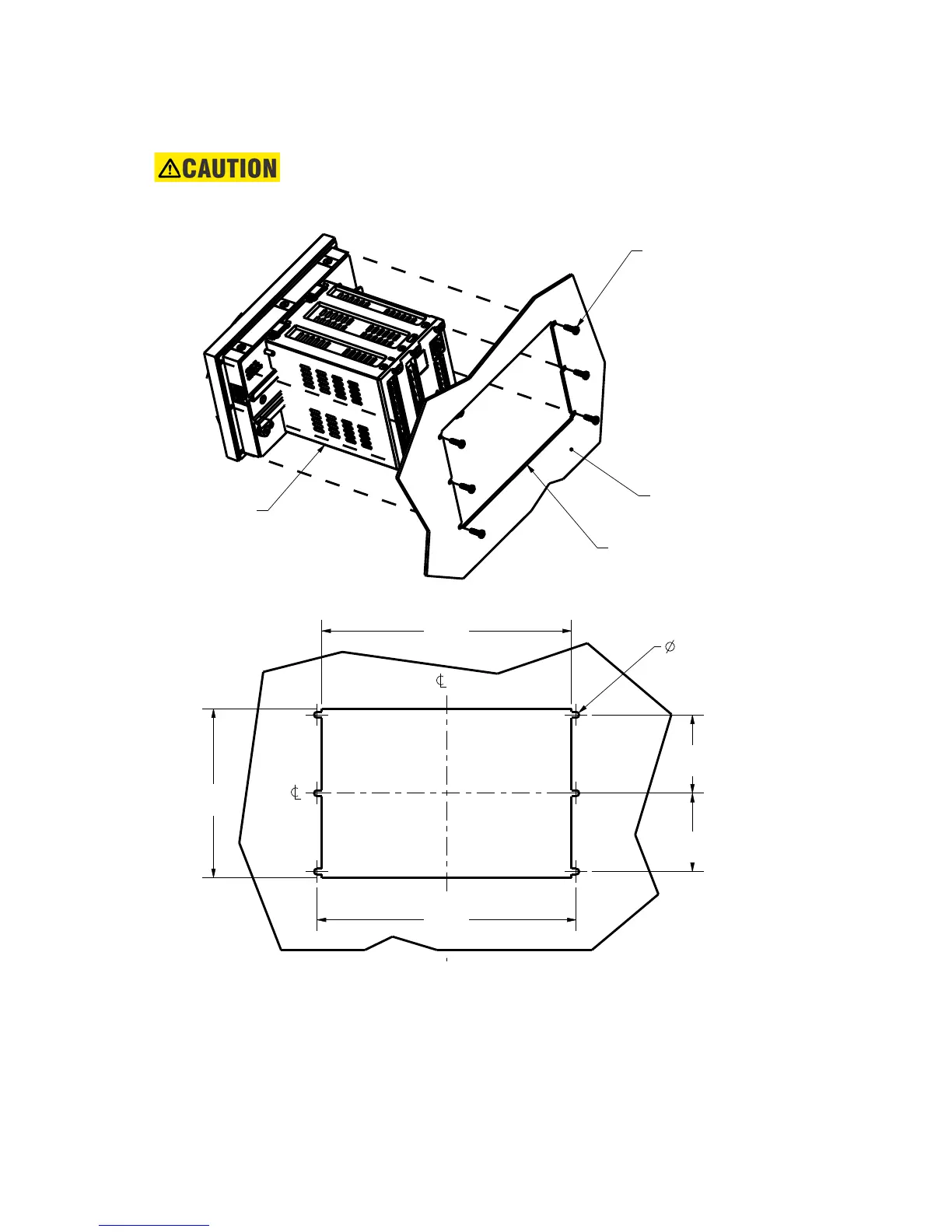
Figure 2-3: Base Unit standard panel mounting and cutout dimensions
5.790
[147]
1.750
[44]
1.750
[44]
5.580
[142]
3.775
[96]
.130 TYP
[3]
FRONT OF THE PANEL
INSTALL RELAY FROM
REAR OF PANEL
CUTOUT AND
MOUNTING HOLES
#4-40X3/8" SELF TAP PAN HD PHILIPS
GE PART# 1402-0017
QTY: 6 (SUPPLIED)
TIGHTENING TORQUE: 8 lb-in
888710A1.CDR

 Loading...


