1–4 MM200 MOTOR MANAGEMENT SYSTEM – INSTRUCTION MANUAL
OVERVIEW CHAPTER 1: INTRODUCTION
Description of the MM200 Motor Management system
The MM200 can be equipped with either of two control panels, or with no control panel.
• Basic control panel: includes pushbuttons for Stop, Start A, Start B, Auto, Manual, and
Reset, and 12 LED status indicators.
• Graphical control panel: includes a 3.5-inch 320 by 240 pixel backlit color LCD screen,
14 pushbuttons and 10 LED indicators, which provide access to actual values, trip and
alarm lists, event records, and setting configuration. A USB port is provided for laptop
computer connection.
The MM200 includes the following input/output capabilities:
• 2 Form A relays, 1 Form C relay
• 7 contact inputs LO power supply; 6 contact inputs HI power supply.
The thermal model uses a standard overload curve with multiplier, and incorporates hot/
cold compensation and exponential cooling.
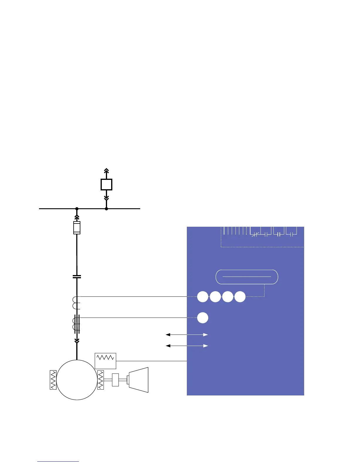
A single-line diagram for the MM200 is shown below.
Figure 1-1: Single line diagram
RS485 - Modbus RTU
Profibus/DeviceNet
52
METERING
A
51R
49
37
46
50G
MOTOR
LOAD
Temperature
Thermistor
Phase CT 3
Ground CT 1
Power Fuse
BUS
MM200
MOTOR MANAGEMENT SYSTEM
Contactor
888739A3.CDR
LO: 7 inputs and 3 outputs
HI: 6 inputs and 3 outputs
LO: 24 V DC
HI: 120 to 240 V AC