CHAPTER 1: INTRODUCTION OVERVIEW
MM200 MOTOR MANAGEMENT SYSTEM – INSTRUCTION MANUAL 1–5
Table 1-1: MM200 protection functions
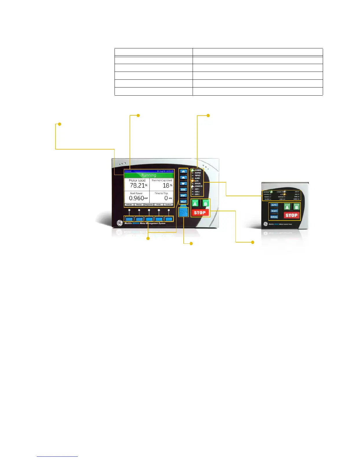
Figure 1-2: MM200 feature overview
ANSI device Description
37 Undercurrent
46 Current unbalance
49 Thermal overload
50G Ground instantaneous overcurrent
51R Locked/stalled rotor, mechanical jam
Graphical display
• Large metering values
• Wide viewing angle
Entry Level Control Panel
• Control keys
• LED Indication
Soft key navigation
• Graphical module control
Front port access
•
USB for laptop connection
Integrated functionality
• Protection, metering, control
LED indication
• Motor status
• Alarm indication
• System status
• Communication status
• Additional user LEDs
Ease of use
• Graphical interface
• Self-description
Mounting options
• DIN Rail
• Through door
888755A1.CDR
Front panel control
• Integrated device control
• Dedicated control keys