3–12 MM200 MOTOR MANAGEMENT SYSTEM – INSTRUCTION MANUAL
GRAPHICAL CONTROL PANEL CHAPTER 3: CONTROL PANEL
interlock functions are disabled, the MM200 will display only 10 successive “Disabled” list
items. If one of the interlock functions were then enabled, then room is made on the
display for the six setpoints which are now functional.
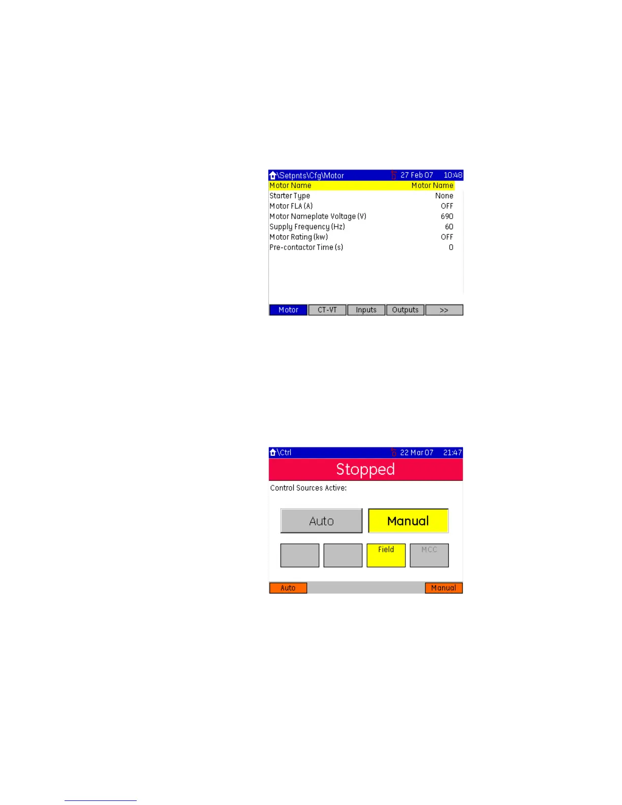
The setpoint pages are in a common format of twelve rows and two columns displaying
setpoint name, value, and units.
The Home > Setpoints > Config > Motor page is shown below.
Figure 3-12: Typical setpoints page, motor setpoints
Diagnostics pages The diagnostic pages are divided into three sections.
• Counters (accumulated system counter data)
• Info (product information)
• Learned (learned values based upon metered data)
Control page This page is used to view the active control mode and switch between Auto/Manual if the
softkeys are enabled.
Figure 3-13: Typical control page display
Refer to the Control Elements section for details on control page functionality.