CHAPTER 4: KEYPAD SETPOINTS S10 ANALOG OUTPUTS
369 MOTOR MANAGEMENT RELAY – QUICKSTART GUIDE 4–53
4.8 S10 Analog Outputs
4.8.1 Analog Outputs
PATH: S10 ANALOG OUTPUTS Ø ANALOG OUTPUT 1(4)
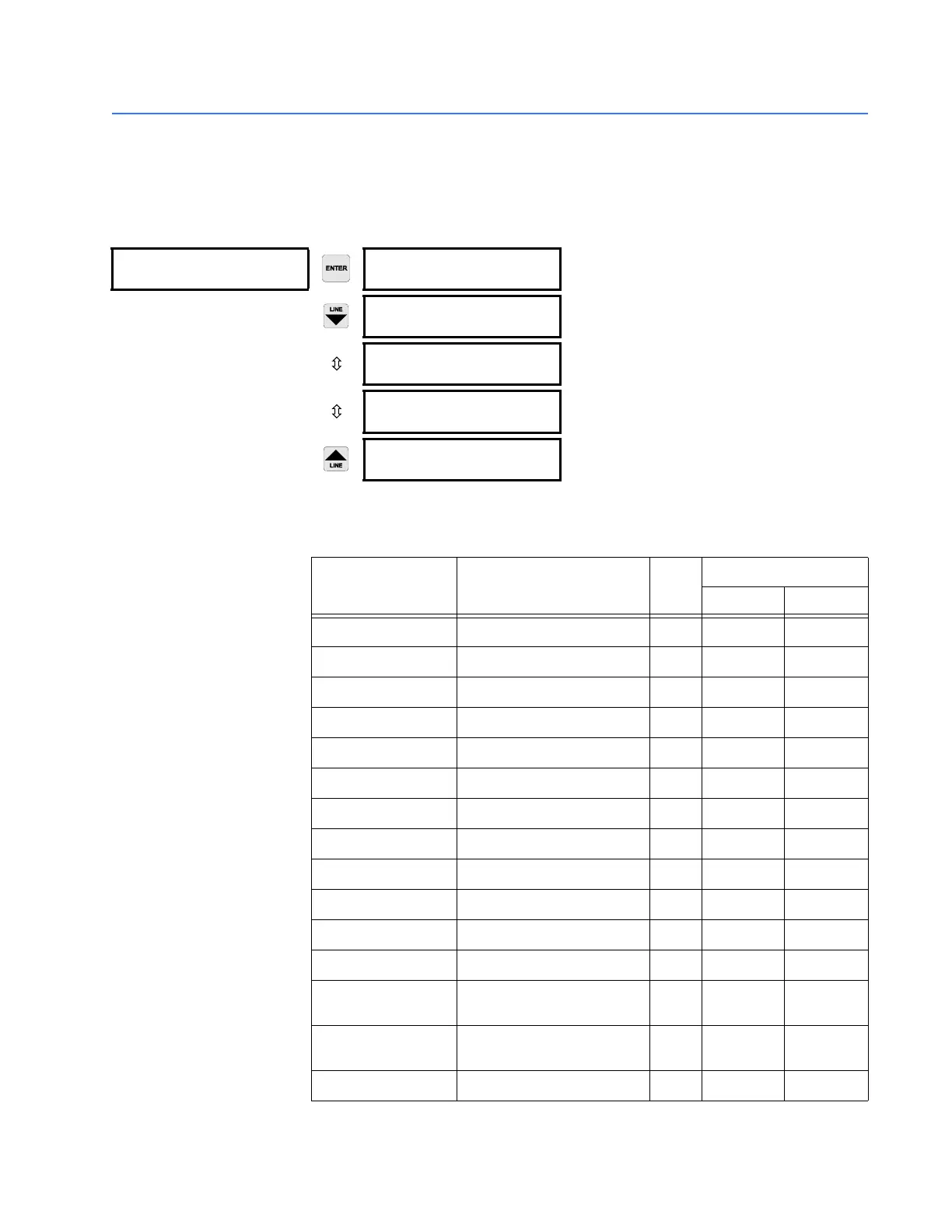
The analog output parameters are indicated in the following table:
ANALOG OUTPUT 1 ANALOG OUTPUT 1:
DISABLED
Range: Disabled, Enabled
ANALOG OUTPUT 1
RANGE: 0-1 mA
Range: 0–1mA, 0–20 mA, 4–20 mA
ANALOG OUTPUT 1:
Phase A Current
Range: See Analog Output selection table
ANALOG OUTPUT 1
MIN: 0 A
Range: See Analog Output selection table
ANALOG OUTPUT 1
MAX: 100 A
Range: See Analog Output selection table
Table 4–2: Analog Output Parameters
PARAMETER NAME RANGE /UNITS STEP DEFAULT
MINIMUM MAXIMUM
Phase A Current 0 to 65535 A 1 0 100
Phase B Current 0 to 65535 A 1 0 100
Phase C Current 0 to 65535 A 1 0 100
Avg. Phase Current 0 to 65535 A 1 0 100
AB Line Voltage 0 to 65000 V 1 3200 4500
BC Line Voltage 0 to 65000 V 1 3200 4500
CA Line Voltage 0 to 65000 V 1 3200 4500
Avg. Line Voltage 0 to 65000 V 1 3200 4500
Phase AN Voltage 0 to 65000 V 1 1900 2500
Phase BN Voltage 0 to 65000 V 1 1900 2500
Phase CN Voltage 0 to 65000 V 1 1900 2500
Avg. Phase Voltage 0 to 65000 V 1 1900 2500
Hottest Stator RTD
–40 to +200°C or
–40 to +392°F
10 200
RTD #1 to 12
–40 to +200°C or
–40 to +392°F
1 –40 200
Power Factor –0.99 to 1.00 0.01 0.01 0.80