NX-8E CONTROL
67
XIV. TERMINAL DESCRIPTIONS
TERMINAL DESCRIPTION
R1 House Telephone Ring (Grey).
R Telephone Ring (Red).
T Telephone Tip (Green).
T1 House Telephone Tip (Brown).
EARTH Earth Ground. Connect to a cold water pipe or a 6 to 10 foot driven rod.
AC AC input. Connect to a 16.5V, 40VA or 50 VA Class ll U.L. approved transformer.
BELL + &
BELL -
If used as a siren output (default), the speaker rating should be 15 watt at 8 or 16 ohm, or 30/40
watt at 4, 8, or 16 ohms. If voltage output is selected in location 37, this output becomes voltage
output, 12VDC, 1 Amp maximum load. NOTE: A 3.3K Ω resistor may be required across the
bell terminals when a 12 VDC siren is used. If no resistor is used, you may experience
voltage leakage into the siren, which will cause these devices to output a small signal.
KP DATA
Connect to the data terminal on the keypads and the expanders. Maximum number of devices
(keypads + expanders) is 32. See AMaximum Wire Run@ chart below.
KP COM Connect to the Common terminal on the keypads and the expanders.
KP POS
Connect to the POS terminal on the keypads and the expanders. Individually, this terminal is
limited to 1 Amp. Combined, this terminal and AUX PWR + are limited to 2 amps total current.
SMOKE+
Smoke detector power 12VDC, 1.5 amps maximum (For those jurisdictions which allow the Priority
zone to be used with smoke detectors.)
COM Connect negative wire of powered devices such as motion detectors and smoke detectors.
AUX PWR+
Connect positive wire of all powered devices except smoke detectors and keypads. Individually,
this terminal is limited to 1 Amp. Combined, this terminal and KP POS are limited to 2 amps total
current.
ZONE 8
Connect to one side of zone 8 loop. Connect the other side to com terminal. Open or short causes
alarm. Zone 8 may be used for a two-wire smoke detector using a 680 Ω E.O.L. resistor.
Connect one side to AUX PWR+ ONLY if using 2-wire smoke. Refer to wiring diagram.
Program location 37, segment 6, option 1.
COM Common (-) terminal for zones 7 & 8. (See the wiring diagram for examples.)
ZONE 7
Connect to one side of zone 7 loop. Connect the other side to COM terminal. Open or short causes
alarm.
ZONE 6 -
ZONE 1
Connect as described for zones 7 & 8. Only zone 8 can be a two-wire zone. (See the wiring
diagram for examples.)
C Closed dry contact rated 1 Amp at 30 Volts. RELAY
2
NO Normally open dry contact rated 1 Amp at 30 Volts.
COM Common used to ground any devices connected to relays.
NC Normally closed dry contact rated 1 Amp at 30 Volts RELAY
1
C Closed dry contact rated 1 Amp at 30 Volts
NOTE: These terminals can be
set for 12VDC. Install J12 for
AUX1 and J13 for AUX2 (See
terminal drawing.)
(See terminal
drawing)
AUX 1-
AUX 4
Connect negative lead of low current device [relay, LED (install 1kΩ resistor in series
with LED), etc.]. Connect positive lead of device to AUX PWR +. Current is limited to
50mA when output is negative, and 250FA when output is positive. Part number #8920
is 4-wire cable.
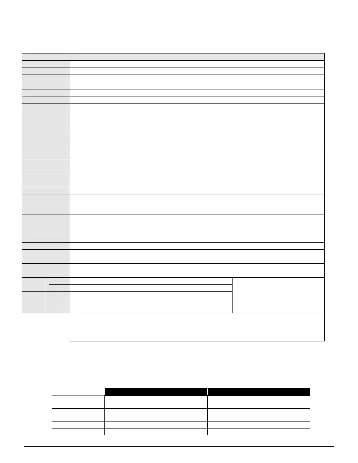
KEYPAD MAXIMUM WIRE RUN
(Note: These numbers are for one keypad at the end of the wire. When connecting more than one keypad to the end
of the wire, a higher gauge wire will be required.)
WHEN CONNECTED TO NX-8E WHEN CONNECTED TO NX320-E
Length in feet Wire Gauge Wire Gauge
250 24 22
500 20 18
1000 18 16
1500 16 14
2500 14 12
 Loading...