NX-8E CONTROL
77
XXII. BOARD INSTALLATION
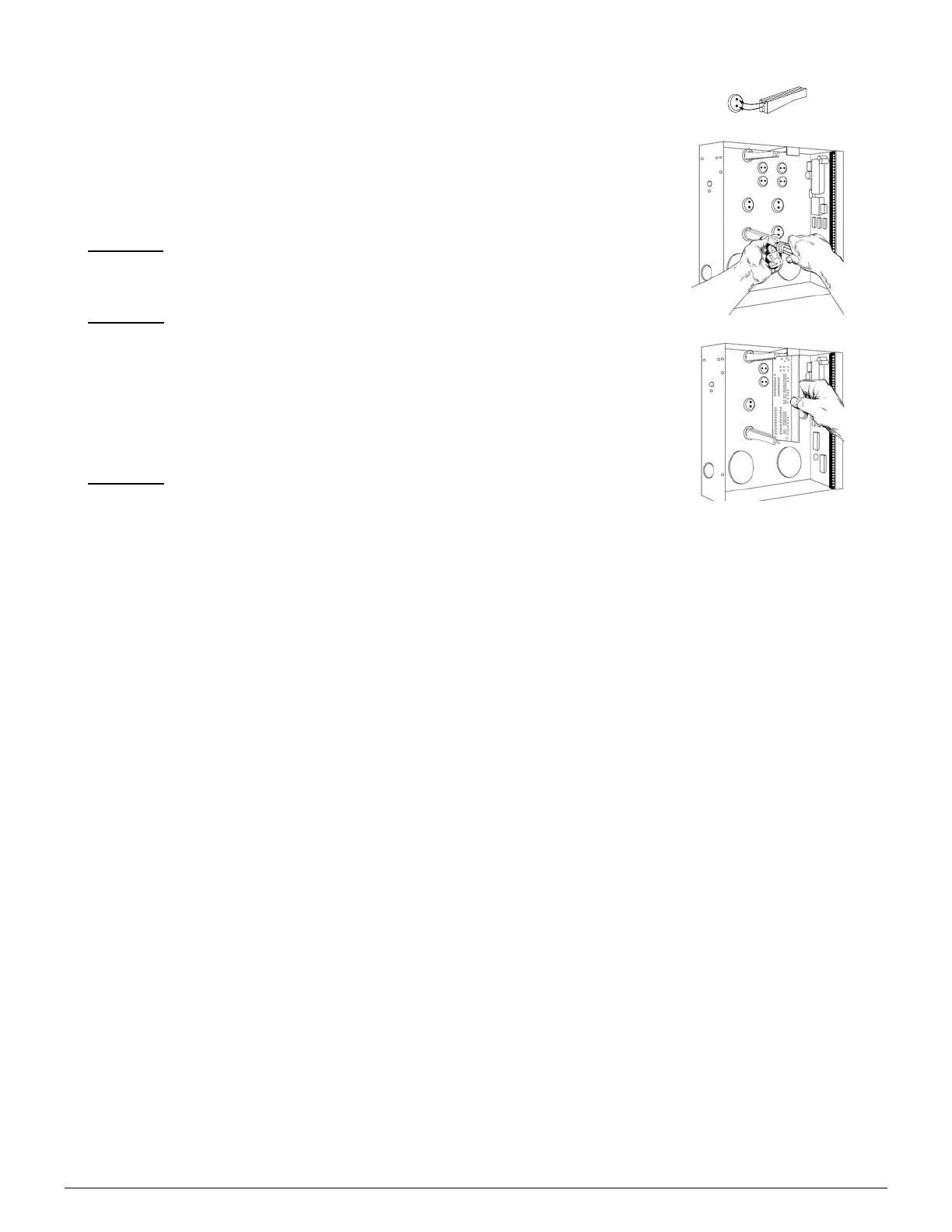
Inside the can, several 2-holed insertion points have been constructed. This
allows for either vertical or horizontal placement of the modules. Notice that
each insertion point has two sizes of holes -a larger hole and a smaller hole.
Diagram 1
: The black plastic PCB guides are grooved on one edge where the
PC board will be seated. The end with the half-moon protrusion fits into the
larger hole. The smaller hole is for the screw.
Diagram 2
: Place the first black plastic PCB guide in the top insertion point,
grooved edge downward. The half-moon protrusion will be in the large hole. It
does not require force. Insert one of the provided screw into the smaller hole
(from inside the can) to secure it in place. A screwdriver should reach through
the notch that runs the length of the guide to tighten the screw. The second
PBC guide should be positioned opposite the first (grooved edge up) and placed
in the lower insertion point, using the same procedures described above. Once
mounted, screw it in securely.
Diagram 3
: The PC Board should slide freely in the grooves of both guides.
 Loading...