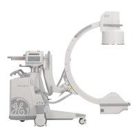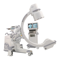
Do you have a question about the GE OEC 9800 C-Arm and is the answer not in the manual?
| Type | Mobile C-Arm |
|---|---|
| X-Ray Tube Type | Rotating anode |
| Digital Imaging | Yes |
| Image Intensifier Size | 9 inches |
| Imaging Modes | Fluoroscopy, Digital Subtraction Angiography (DSA), Cine |
| Flat Panel Detector Size | Not applicable |
| X-Ray Tube Voltage | 40 - 120 kVp |
| C-Arm Rotation | 180 degrees |
| Power Requirements | 200-240 VAC, 50/60 Hz |
Explains the manual's content and function for field service engineers and technicians.
Defines the target users as trained engineers and technicians for installation, maintenance, and calibration.
Guides users on navigating the manual's structure and finding information.
Lists the part numbers and descriptions for various cover components.
Illustrates the assembly of various cover components for the C-Arm system.
Lists parts for the Image Intensifier (II) and camera components.
Provides a visual breakdown of the Image Intensifier (II) and camera components.
Lists components for the X-Ray tube and collimator assembly.
Details the assembly of the X-Ray tube and collimator assembly.
Lists components for the internal cover and related parts.
Shows the exploded view of internal cover components and related parts.
Lists parts for the battery and power panel assembly.
Illustrates the components of the battery and power panel assembly.
Lists components for the stator capacitor and transformer.
Details the exploded view of the stator capacitor and transformer components.
Lists components for the power panel assembly.
Shows the exploded view of the power panel and its associated parts.
Lists components for the electronic assemblies.
Provides a visual breakdown of the electronic components and assemblies.
Lists components for the card rack assembly.
Illustrates the assembly of the card rack and its internal components.
Lists components for the IGBT/Snubber and tank assembly.
Details the exploded view of the IGBT/Snubber and tank assembly.
Lists components for the power supply unit.
Shows the exploded view of the power supply unit and its components.
Lists parts for the control panel and L-Arm components.
Illustrates the assembly of the control panel and L-Arm components.
Lists components for the main control panel interface.
Provides a visual breakdown of the main control panel interface.
Lists components for the first part of the L-Arm assembly.
Shows the first part of the exploded view for the L-Arm assembly.
Lists components for the second part of the L-Arm assembly.
Details the second part of the exploded view for the L-Arm assembly.
Lists components for the third part of the L-Arm assembly.
Presents the final part of the exploded view for the L-Arm assembly.
Lists components for the 9-inch flip-flop mechanism.
Illustrates the exploded view of the 9-inch flip-flop mechanism.
Lists components for the 12-inch flip-flop mechanism.
Shows the exploded view of the 12-inch flip-flop mechanism.
Lists components for the vertical column and cross arm assembly.
Details the exploded view of the vertical column and cross arm assembly.
Lists components for the cross arm brake assembly.
Illustrates the exploded view of the cross arm brake assembly.
Lists components for the cross arm housing mount.
Shows the exploded view of the cross arm housing mount.
Lists components for the cross arm brake and bearing.
Details the exploded view of the cross arm brake and bearing components.
Lists components for the cross arm bearings.
Illustrates the exploded view of the cross arm bearings.
Lists components for the first part of the rear steering system.
Shows the first part of the exploded view for the rear steering system.
Lists components for the second part of the rear steering system.
Presents the second part of the exploded view for the rear steering system.
Lists components for the rear brake assembly.
Illustrates the exploded view of the rear brake assembly.
Lists components for the front caster assembly.
Shows the exploded view of the front caster assembly.
Lists components for the steering chain and cable pusher.
Details the exploded view of the steering chain and cable pusher.
Lists components for the rear caster assembly.
Illustrates the exploded view of the rear caster assembly.
Lists components for the first part of the Super C II camera.
Shows the first part of the exploded view for the Super C II camera.
Lists components for the second part of the Super C II camera.
Presents the second part of the exploded view for the Super C II camera.
Lists components for the Super C X-Ray tube assembly.
Details the exploded view of the Super C X-Ray tube assembly.
Lists components for the Super C collimator assembly.
Shows the exploded view of the Super C collimator assembly.
Lists components for the Super C L-Arm assembly.
Illustrates the exploded view of the Super C L-Arm assembly.
Lists components for the Super C Flip-Flop mechanism.
Presents the exploded view of the Super C Flip-Flop mechanism.


