Appendix B - Settings and Signals
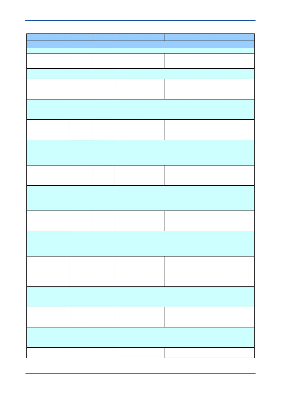
MENU TEXT COL ROW DEFAULT SETTING AVAILABLE OPTIONS
DESCRIPTION
Command that allows all Statistics and Channel Diagnostics to be reset.
Ch Diagnostics 15 40 Invisible
Visible
Setting that makes visible or invisible Channel Diagnostics on the LCD. The diagnostic is reset by either IED’s powering down or using the
‘Reset Statistics’ cell.
Data CD Status 15 41
Fail
SCC Absent
Indicates when the DCD line (pin 1 on EIA232 Connector) is energized.
OK = DCD is energized
FAIL = DCD is de-energized
Absent = 2nd Rear port board is not fitted
FrameSync Status 15 42
Fail
SCC Absent
Indicates when the message structure and synchronization is valid.
OK = Valid message structure and synchronization
FAIL = Synchronization has been lost
Absent = 2nd Rear port board is not fitted
Unavailable = Hardware error present
Message Status 15 43
Fail
SCC Absent
Indicates when the percentage of received valid messages has fallen below the ‘IM Msg Alarm Lvl’ setting within the alarm time period.
OK = Acceptable ratio of lost messages
FAIL = Unacceptable ratio of lost messages
Absent = 2nd Rear port board is not fitted
Unavailable = Hardware error present
Channel Status 15 44
Fail
SCC Absent
Indicates the state of the InterMiCOM communication channel.
OK = Channel healthy
FAIL = Channel failure
Absent = 2nd Rear port board is not fitted
Unavailable = Hardware error present
IM H/W Status 15 45
Fail
SCC Absent
SCC Read Error
SCC Write Error
Indicates the state of InterMiCOM hardware
OK = InterMiCOM hardware healthy
Read or Write Error = InterMiCOM failure
Absent = 2nd Rear port is not fitted or failed to initialize.
Loopback Mode 15 50 Disabled
Internal
External
Setting to allow testing of the InterMiCOM channel. When ‘Internal’ is selected, only the local InterMiCOM software functionality is tested,
whereby the IED will receive its own sent data. ‘External’ setting allows a hardware and software check, with an external link required to
jumper the sent data onto the receive channel.
During normal service condition Loopback mode must be disabled.
Test Pattern 15 51 0xFF
From 0x00 to 0xFF in steps of 1
[Binary Flags (8 bits)]
 Loading...


