Service Tool and Configuration
2030047-001A Patient Data Module 4-11
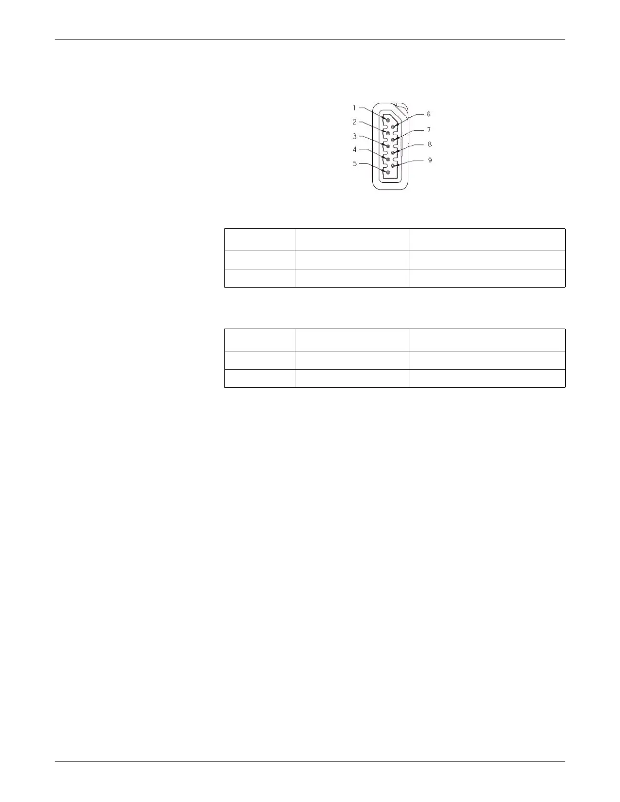
4. Measure voltages indicated below using the digital voltmeter.
435A
To calibrate Analog-Out ECG, measure voltage across the following pins.
To calibrate Analog-Out IP, measure voltage across the following pins.
5. Type in or use the scroll buttons to enter the measured voltage from the digital
voltmeter.
6. Click OK to confirm the measured voltage.
NOTE
Perform calibration if the main cpu board is replaced.
After calibration perform the checkout procedures provided in the host
patient monitor service manual.
Pin Wire color Signal name
1 Brown ECG_ANALOG_OUT
6 Green ANALOG_RETURN
Pin Wire color Signal name
2 Red BP_ANALOG_OUT
6 Green ANALOG_RETURN