3. Operating in Phased Array Mode
PHASOR XS Operating Manual Page 41
can be manually entered as described in Section 3.6.4.
To ensure that the reference reflector is detected by
each beam angle, the Amplitude-Cycle-Diagram is
displayed along with the sector scan throughout the
standard recording process. Created as the probe is
moved over the reference reflector
(Figure 3-8), this
curve represents the reflected amplitude obtained for
each beam angle. The instrument requires that a valid
amplitude be measured for each beam angle before the
TCG reference point can be recorded (Section 3.6.1).
When operating in TCG mode
will appear on the
display screen. Before using the TCG Function do the
following:
• Ensure that all instrument settings (PULSER, RE-
CEIVER, etc.) have been made. Changing these
settings after the TCG reference points are input will
affect the accuracy of measurement.
FIGURE 3-7—Why compensation may be needed
Step 2: To unlock the knob, change the setting of dB
STEP to some value other than LOCK.
NOTE: Both knobs are disabled whenever operating
in Knob Emulator mode
.
3.6 Operating in TCG Mode (Phased
Array)
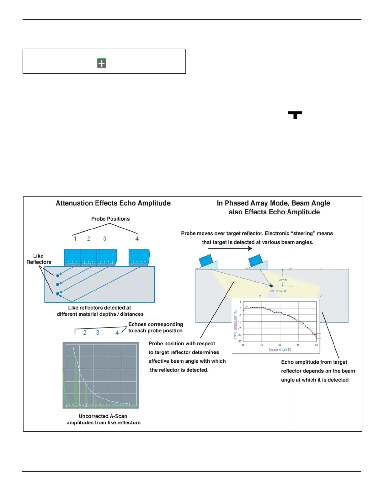
The depth at which identical reflectors occur causes
variation in the amplitude of resulting ultrasonic echoes.
In phased-array sector-scan mode, the TCG feature
compensates for the natural signal decay that results
from attenuation, the influence of “distance laws,” and
also the effect of beam angle on echo
amplitude (Figure 3-7).
To account for the effect of beam angle on echo
amplitude, TCG reference recording requires that each
reference reflector be detected by every beam angle
(described in Section 3.6.1). Alternatively, TCG points