3. Operating in Phased Array Mode
Page 42 PHASOR XS Operating Manual
• Carefully calibrate the instrument for the probe /
material combination prior to beginning the TCG
recording process.
• Set the MAT THICKNESS and LEG values so that
all reference reflectors will fall within the displayed
sector. These settings can not be adjusted while
recording TCG points.
• TCG reference points (up to 15) must be recorded
by obtaining an A-Scan echo of a representative
reflector or manually entered using the TCG EDIT
Submenu. The reference points allow the instru-
ment to calculate and compensate for the effect of
material attenuation on reflector-amplitude height.
The dynamic range of the TCG function is 40 dB.
Maximum curve slope is 6 dB per microsecond.
Successive data points do not have to decrease in
amplitude. That is, the TCG curve does not have to
have a constantly descending slope.
3.6.1 Recording the TCG Reference
Points
TCG reference points are typically taken from a standard
with equally sized reflectors (holes) located at various
material depths. The primary echo from each of these
points (for up to a total of 15 echoes) are recorded. When
TCG is active, the instrument compensates for different
material thickness and different detecting-beam angles
by applying a varying gain level to echoes at material
depths other than the baseline depth. Only one set of
TCG reference points can be stored at a time. To record
TCG reference points:
Step 1: A-Gate is used to record the reference echoes.
Set GATE START and WIDTH to evaluate only the se-
lected reference echo. Set THRESHOLD to 5% in order
to include any signal height above 5% FSH.
Step 2: Access the NRM/TCG Submenu (located in the
UT Menu) by pressing
.
Step 3: Start the recording process by pressing (two
times)
next to RECORD so that POINT 1 appears.
Couple the phased array probe to the test standard so that
at least one “step” segment on the display’s left side (see
Figure 3-9) indicates the reflector’s presence. As seen in
Figure 3-9, display segments move to the right from their
baseline position by an amount that’s proportionate to their
maximum amplitude. Note that changing Gain setting or
moving the A-Gate THRESHOLD will alter the amplitude
at which this reflector is detected in A Gate.
NOTE: During the recording process, the gain applied
to one or more beam group segments can be reduced
to eliminate the effect of an undesired reflector (such
as a geometric feature that is detected by these spe-
cific segments) on the recording of a TCG point. See
Section 3.6.2 to select a region of interest during the
TCG-point recording process.
NOTE: The cyclic gain feature (
Section 3.6.3) adds an
incremental amount of gain to each beam group.
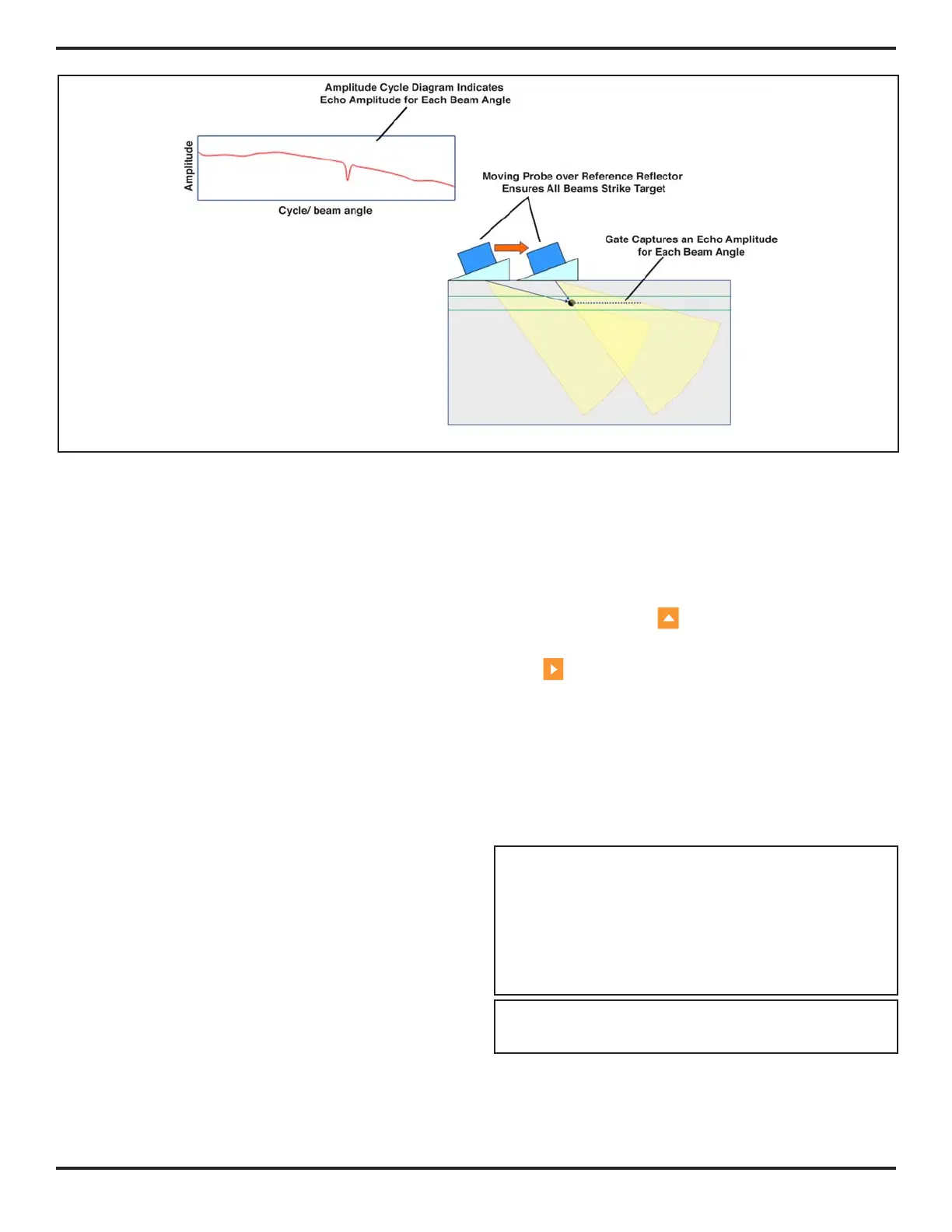
FIGURE 3-8—The Amplitude Cycle Diagram indicates the TCG-reference amplitude recorded at each beam angle.