4. Conventional Operation: Menu System, Keypad, and Displays
Page 60 PHASOR XS Operating Manual
note that the range can vary from 0.040 to 300 inches.
Step 4: The display’s horizontal range will remain as
set.
4.8.2 Setting the Display Delay
The display delay function shifts the displayed A-Scan to
the left or right. This function is used to set the instrument’s
viewing window. To set the display delay
Step 1: Activate the Home Menu by pressing
. Func-
tions will appear down the left side of the display sreen.
Step 2: Press
next to the selection titled DISPLAY
DELAY.
Step 3: To change the display delay turn the function knob.
You’ll note that the displayed echoes shift to the left or
right.
4.9 Calibrating the Instrument
4.9.1 Pre-calibration Check List
To improve the accuracy and quality of your calibration, be
sure that the following conditions are met before launching
the calibration function:
• Probe installed
• DUAL (RECEIVER) setting must match probe
• Set the material type (
Section 2.4)
• Recommended that DISPLAY DELAY be set to 0
• PRF set to AUTO.
• TCG—Turned OFF
• Recommended that REJECT be set to 0.
4.9.2 Using AUTOCAL to Calibrate the
Instrument
(Read the following while reviewing Figure 4-12)
Step 1: From the SETUP Menu, activate the AUTOCAL
Submenu by pressing
below it. Four functions will
appear down the left side of the display screen.
Step 2: Press
next to the selection titled S-REF1 and
turn the function knob until the value of S-REF1 matches
the thickness of the thinner calibration standard.
Step 3: Press
next to the selection titled S-REF2 and
turn the function knob until the value of S-REF2 matches
the thickness of the thicker calibration standard.
Step 4: Apply couplant and couple the probe to the thin-
ner calibration standard. Press
next to the selection
titled A START. Turn the function knob (this will shift the
starting point of the A-Gate) until the A-Gate lies over the
echo corresponding to the thinner standard’s thickness
(
Figure 4-12).
Step 5: Press
next to the selection titled RECORD.
The value in the function box will change from “OFF” to
“S-REF1?”. While maintaining the signal in the A-Gate,
NOTE: The instrument’s AUTOCAL Function applies
only to conventional operation, not to phased-array
operation.
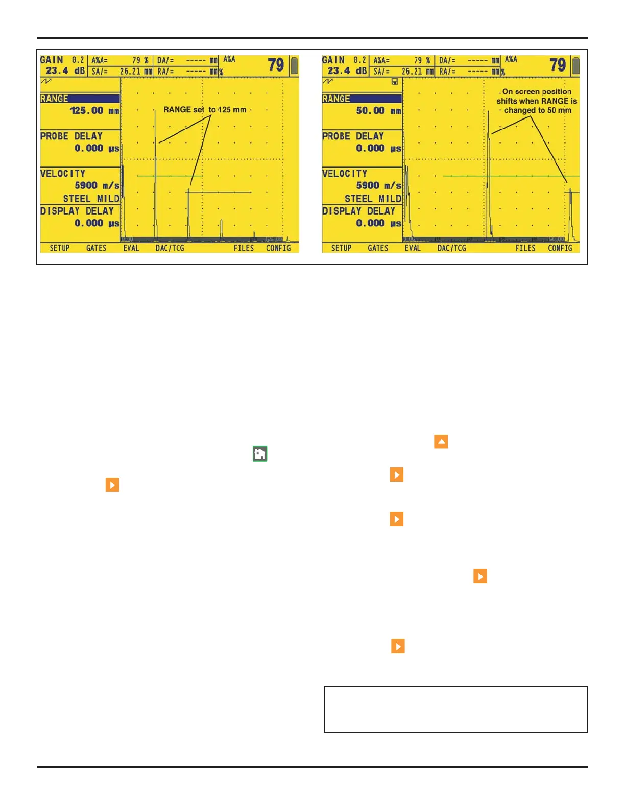
FIGURE 4-11—Effect of A-Scan Range Adjustment