5. Making Conventional Measurements
Page 76 PHASOR XS Operating Manual
prevent you from modifying the PROBE NAME or any of
the other settings described in Step 4.
Step 4: If the user-defined probe type (PROBE #0) is
selected, you must then select the DGS PROBE sub-
menu and input the characteristics for the probe you’ve
connected including:
XTAL FREQUENCY—The probe’s frequency rating
EFF. DIAMETER—The probe element’s effective
diameter rating
DELAY VELOCITY—User determined delay-line
velocity
Note that these characteristics can’t be changed for any
probes other than PROBE #0.
5.14.2 Record the Reference Echo that
Defines the DGS Curve
Prior to generating the DGS curve, a test standard with
a known reflector must be used to define a reference
point. Acceptable test standards include these reference
types:
• BW—Backwall echo with reference defect size de-
fined as infinity
• SDH—Side Drilled Hole with a reference defect size
defined as the hole’s diameter
• FBH—Flat Bottom Hole with a reference defect size
equal to the hole’s facial diameter
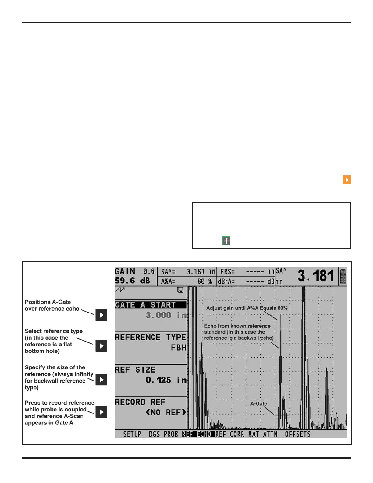
Follow these steps and
Figure 5-9 to record a reference
echo:
Step 1: Select the REF ECHO submenu, then the REFER-
ENCE TYPE function. Once activated, this function allows
you to select one of the three reference types described
above, and specify the size of the known standard’s refer-
ence flaw.
Step 2: Couple the probe to the known standard,
capture the reference flaw so that it’s reflected echo is
displayed on the instrument’s A-Scan, and adjust the
A-Gate’s starting point to ensure that the resulting echo
triggers the gate.
Step 3: Adjust the gain knob until the reference flaw’s
A-Scan peak measures 80% of FSH (A%A = 80%).
Step 4: With the probe coupled to the standard, and the
reference flaw’s echo captured by the A-Gate, press
next to the RECORD REF function to store a DGS refer-
ence echo.
NOTE: The AUTO 80 function allows for automatic ap-
plication of gain to set A-Gate’s triggering echo to 80%
of full screen height. This function can be accessed
at any time via the knob emulator menu (activated by
pressing
).
FIGURE 5-9—Recording a DGS reference point from which a DGS Curve will be generated.