4. Conventional Operation: Menu System, Keypad, and Displays
PHASOR XS Operating Manual Page 51
GATE B Submenu (Refer to
Section 5.1.1)
• GATE B START—Sets the beginning position of B gate on the
A-Scan.
• GATE B WIDTH—Sets the width of B gate on the A-Scan.
• B THRESHOLD—Sets the height of B gate.
• TOF MODE—Indicates whether an A-Scan echo’s flank, or peak is
evaluated by the B gate. (Refer to Section 5.1.2)
GATEMODE Submenu
• A GATE LOGIC—Determines whether the gate alarm is triggered
when a signal crosses the gate or does not cross the A gate. (Refer to
Section 5.1.3)
• B GATE LOGIC—Determines whether the gate alarm is triggered
when a signal crosses the gate or does not cross the B gate. (Refer to
Section 5.1.3)
• OUTPUT SELECT—Set alarm light and output to indicate when one
or both gates are triggered (Refer to Section 5.1.3)
EVAL Menu
TRIG Submenu (Refer to Section 5.2)
• PROBE ANGLE—Input the angle of a connected angle beam probe.
• THICKNESS—Sets the test-piece material thickness for angle-beam
measurements.
• X VALUE—Input the specified value from the angle beam probe’s
BIP to front edge.
• COLOR LEG—Indicates in which leg a reflector is located. (Used
with angle beam probes.)
RESULTS Submenu (Refer to Section 5.3)
• READING 1 THROUGH READING 4—Selects the measurement
displayed in each of the four Reading Boxes. (Refer to Section 5.3)
RESULTS2 Submenu (Refer to Section 5.3)
• MODE—Set the large reading box to display one or two results
• READING 5 / LRG—Select the measurement displayed in the large
or fifth (if the large box is split) result box.
• READING 6—Select the measurement displayed in the sixth (when
the large box is split) result box.
GATE A Submenu (Refer to Section 5.1.1)
• GATE A START—Sets the beginning position of A-Gate on the A-
Scan.
• GATE A WIDTH—Sets the width of A-Gate on the A-Scan.
• A THRESHOLD—Sets the height of A gate on the A-Scan.
• TOF MODE—Indicates whether an A-Scan echo’s flank or peak is
evaluated by the A gate.
GATE B Submenu (Refer to Section 5.1.1)
• GATE B START—Sets the beginning position of B-Gate on the A-
Scan.
• GATE B WIDTH—Sets the width of B-Gate on the A-Scan.
• B THRESHOLD—Sets the height of B gate on the A-Scan.
• TOF MODE—Indicates whether an A-Scan echo’s flank or peak is
evaluated by the B gate.
FILES Menu
FILENAME Submenu (Refer to Sections 6.1 and 6.6)
• FILENAME—Select stored files or input new data set or report
name.
• SOURCE/DEST—Indicates the device to or from which data is sent.
• ACTION—Recalls or deletes the selected file and saves edits to
data sets and reports.
• ENTER— Causes specified ACTION to occur.
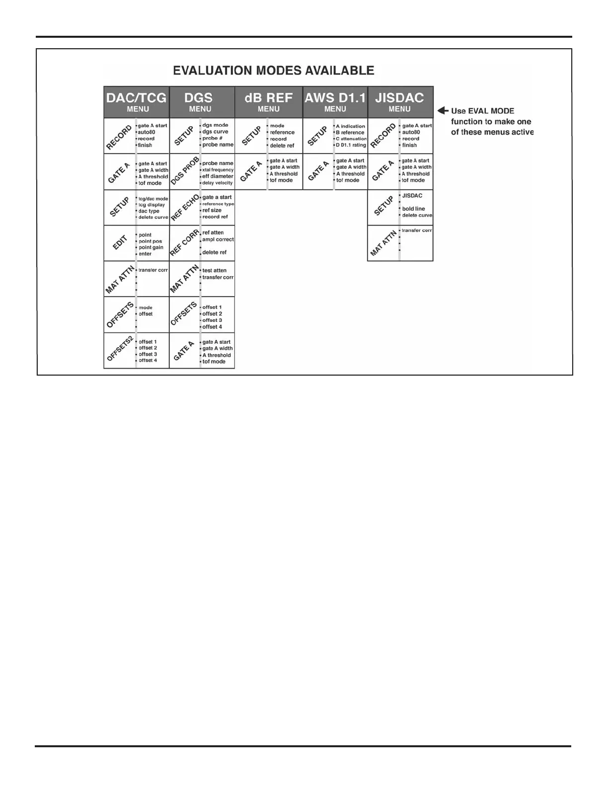
FIGURE 4-4—The instrument’s various evaluation menu selections are activated via the EVAL MODE function located in
the EVAL Menu. Once selected, the active evaluation mode is added to the HOME Menu.