5. Making Conventional Measurements
Page 68 PHASOR XS Operating Manual
Reference results (identified with “r”) Behavior
Based on EVAL MODE
DAC—% Amplitude or dB compared to corre-
sponding DAC curve point
TCG—% Amplitude or dB compared to TCG
reference level
dB REF—% Amplitude or dB compared to refer-
ence level
DGS—% Amplitude or dB compared to curve /
size selected
JISDAC—% Amplitude or dB compared to JIS
LINE (H, M, or L) set to BOLD
NONE—% Amplitude or dB compared to gate
threshold height
• CLS—JIS CLASS (I, II, III, or IV) available only
when JISDAC evaluation mode is active.
• ERS—Evaluates the reflected echo (DGS Mode)
and calculates the Equivalent Reflector Size
• Gt—DGS test gain, which initializes the DGS curve’s
max height at 80% FSH.
• Gr—DGS reference gain, which represents the
instrument gain at which the reference echo’s peak
reaches 80% FSH.
• OFF—No reading will be displayed in the reading
box.
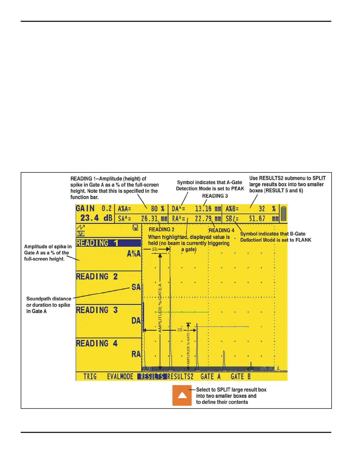
The measured readings can be displayed in any of the
up-to-six small reading boxes at the top of the display
screen. Note that when four small results are shown,
another result can be displayed in the large reading box
(see
Figure 5-5).
The large result box can also be split into two smaller
boxes, allowing up to six results to be displayed
simultaneously:
FIGURE 5-5—The RESULTS submenu is used to specify which measured values to display.