CHAPTER 5: SETPOINTS
PQMII POWER QUALITY METER – INSTRUCTION MANUAL 5–19
5.3 S2 System Setup
5.3.1 Current and Voltage Configuration
Note
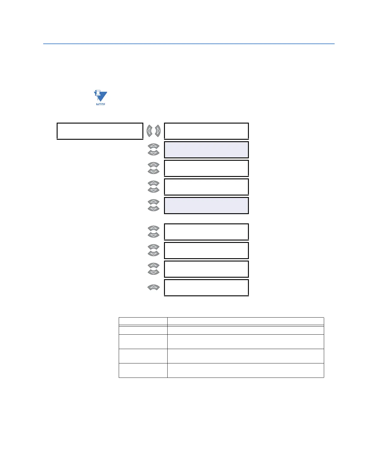
The shaded setpoints below must be set to a value other than “Off” to clear the Critical
Setpoints Not Stored alarm.
PATH: SETPOINTS ÖØ S2 SYSTEM SETUP Ö CURRENT/VOLTAGE CONFIG.
• PHASE CT WIRING: The table below indicates the required connection per setpoint
setting.
If the “A and B Only”, “A and C Only”, or “A Only” connection is selected, the neutral
sensing must be accomplished with a separate CT.
• PHASE CT PRIMARY: Enter the primary current rating of the phase current
transformers. All three phase CTs must have the same rating. For example, if 500:5 CTs
are used, the
PHASE CT PRIMARY value is entered as “500”. The PHASE CT PRIMARY factory
default is “Off”. While set to “Off”, the PQMII is forced to an alarm state as a safety
CURRENT/ [Z]
VOLTAGE CONFIG.
PHASE CT WIRING:
Phases A, B, AND C
Range: A, B, and C, A and B only, A and
C only, A only
MESSAGE
PHASE CT PRIMARY:
OFF A
Range: 5 to 12000 A in steps of 5 or Off
MESSAGE
NEUTRAL CURRENT
SENSING: OFF
Range: Off, Separate CT, Calculated
MESSAGE
NEUTRAL CT PRIMARY:
100 A
Range: 5 to 6000 A in steps of 5
MESSAGE
VT WIRING:
OFF
Range: Off, 4 Wire Wye / 3 VTs, 4 Wire
Wye / Direct, 4 Wire Wye / 2
VTs, 3-Wire Delta / 2 VTs, 3
Wire Direct, Single Phase Direct
MESSAGE
VT RATIO:
1.0:1
Range: 1.0 to 3500.0 in steps of 0.1
MESSAGE
VT NOMINAL SECONDARY
VOLTAGE: 120 V
Range: 40 to 600 V in steps of 1
MESSAGE
NOMINAL DIRECT INPUT
VOLTAGE: 600 V
Range: 40 to 600 V in steps of 1
MESSAGE
NOMINAL SYSTEM
FREQUENCY: 60 Hz
Range: 50 Hz, 60 Hz
Setpoint Value Required CT Connection
A,B, and C CTs are connected to phase A, B and C inputs.
A and B Only
CTs are connected to phase A and B only. Phase C input is left
open. The value for phase C is calculated by the PQMII.
A and C Only
CTs are connected to phase A and C only. Phase B input is left
open. The value for phase B is calculated by the PQMII.
A Only
CT is connected to phase A only. Phase B and C inputs are left
open.
The values for phase B and C are calculated by the PQMII.
 Loading...


