5–30 PQMII POWER QUALITY METER – INSTRUCTION MANUAL
CHAPTER 5: SETPOINTS
Z Continue entering characters and spaces until the desired message is
displayed. If a character is entered incorrectly, press the
ENTER key
repeatedly until the cursor returns to the incorrect position and re-enter
the character.
• PULSE INPUT 1(4) VALUE: Enter a value in this setpoint that will be equivalent to 1
pulse input on the switch input assigned to Pulse Input 1(4); i.e., 1 pulse = 100 kWh. The
accumulated value is displayed in actual values under
A1 METERING ÖØ PULSE INPUT
COUNTERS
ÖØ PULSE INPUT 1(4).
• PULSE INPUT TOTAL: This setpoint defines which pulse inputs to add together. For
example, if the selection is this setpoint is “1+2+3”, the
PULSE INPUT 1, PULSE INPUT 2
and
PULSE INPUT 3 values shown in A1 METERING ÖØ PULSE INPUT COUNTERS ÖØ
PULSE INPUT 1(4)
will be added together and displayed in A1 METERING ÖØ PULSE
INPUT COUNTERS ÖØ PULSE IN 1+2+3.
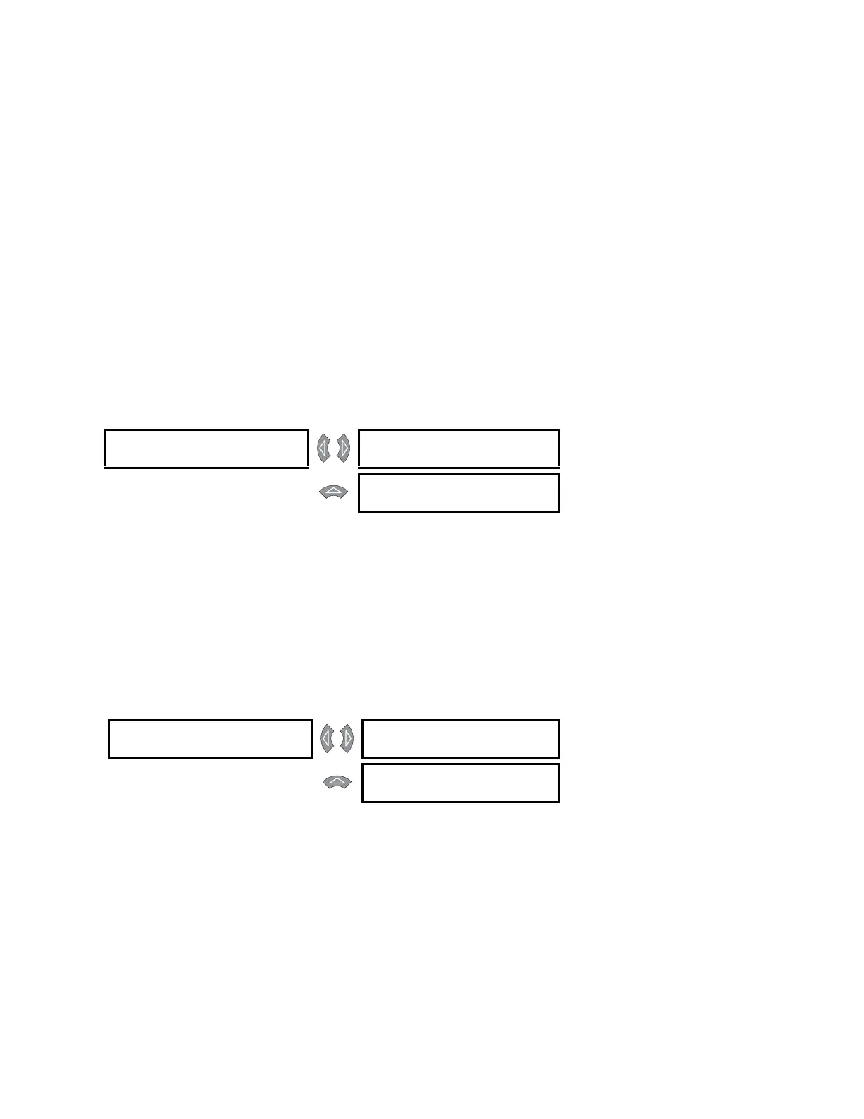
5.3.7 Data Logger
PATH: SETPOINTS ÖØ S2 SYSTEM SETUP ÖØ DATA LOGGER
The data logger operation is only configurable using the EnerVista PQMII Setup Software.
On occasions it may be necessary to stop the data loggers using the PQMII keypad and
then a computer to extract the logged information. The
STOP DATA LOG 1(2) setpoints allow
the user to stop the respective data log. These setpoints also display the current status of
the respective data logger. Refer to 7.6 Data Logger Implementation for a detailed
implementation description.
5.3.8 Voltage Disturbance
PATH: SETPOINTS ÖØ S2 SYSTEM SETUP ÖØ VOLTAGE DIST. RECORDER
• SAG LEVEL: When the voltage on any phase drops below this level a Sag condition
occurs. During this condition, the average voltage and duration of the disturbance are
calculated. The condition ends when the level increases to at least 10% of nominal
plus pickup of the
SAG LEVEL setting. This hysteresis is implemented to avoid nuisance
alarms due to voltage fluctuations. If the duration logged was less then or equal to 1
minute an event with a sag type will be logged. If the duration was greater then 1
minute an event with an undervoltage type will be logged when this feature is
configured.
• SWELL LEVEL: When the voltage on any phase increases above this level a swell
condition occurs. During a swell condition the average voltage and duration of the
DATA LOGGER [Z] STOP DATA LOG 1:
NO (STOPPED)
Range: No, Yes
MESSAGE
STOP DATA LOG 2:
NO (STOPPED)
Range: No, Yes
VOLTAGE DIST. [Z]
RECORDER
SAG
LEVEL ≤ 80% Nominal
Range: 20 to 90% of Nominal VT in
steps of 1
MESSAGE
SWELL
LEVEL ≥ 130% Nominal
Range: 110 to 150% of Nominal VT in
steps of 1
 Loading...


