– 26 –
(Continued Next Page)
4. Pull the outer tub assembly out of the washer
cabinet.
Caution: Care must to taken when reinstalling and
sealing the drain hose to the outer tub to ensure
there is no water leakage.
When installing, apply a thin coat of sealing
compound (part no. WH60X15) to the inner surface
of the drain hose.
3. Lift the outer tub up and disengage the
suspension rod assemblies from each corner of
the outer tub.
Disengage
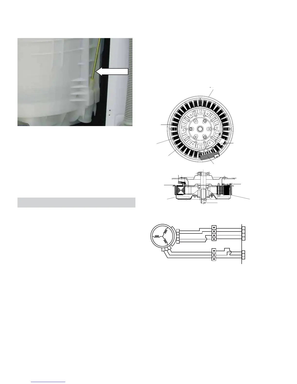
Motor Assembly
The washer has a direct drive pulse width •
modulation motor that does not utilize a belt,
transmission, or mechanical brake.
The motor assembly is composed of a coil •
wound stator, Hall sensor, and permanent
magnet rotor.
The motor varies speed and torque when the •
pulse width modulated voltage from the inverter
changes frequency.
The motor reverses rotational direction when •
the inverter reverses electrical polarity to the
motor.
COIL
STATOR
PERMANENT MAGNET
PERMANENT
MAGNET
HALL SENSOR
POWER
ROTOR
SHAFT
STATOR
ROTOR NUT
RotorROTOR
POWER
HALL SENSOR ASSEMBLY
The washer motor has an approximate resistance
value of 8 Ω between any two of the three wires:
Blue to red - 8 • Ω
Red to yellow - 8 • Ω
Blue to yellow - 8 • Ω
Resistance can be measured at the yellow, 3-pin
connector on the inverter board or at the motor. (See
Inverter and Main Board Pin Connectors.)
Yellow
Dk. Blue
Red
Yellow
Dk. Blue
Red
Yellow
Dk. Blue
Red
Yellow
Brown
4
5
2
3
1
2
3
4
12
345
HALL
SENSOR
1
2
3
MOTOR
Dk. Blue
Red
Yellow
Brown
1
2
3
Dk. Blue
 Loading...