– 30 –
3. Remove the clutch coupler assembly.
4. Disconnect the wiring connector from the clutch
motor.
5. Remove the two 10-mm hex-head screws that
hold the clutch motor in place.
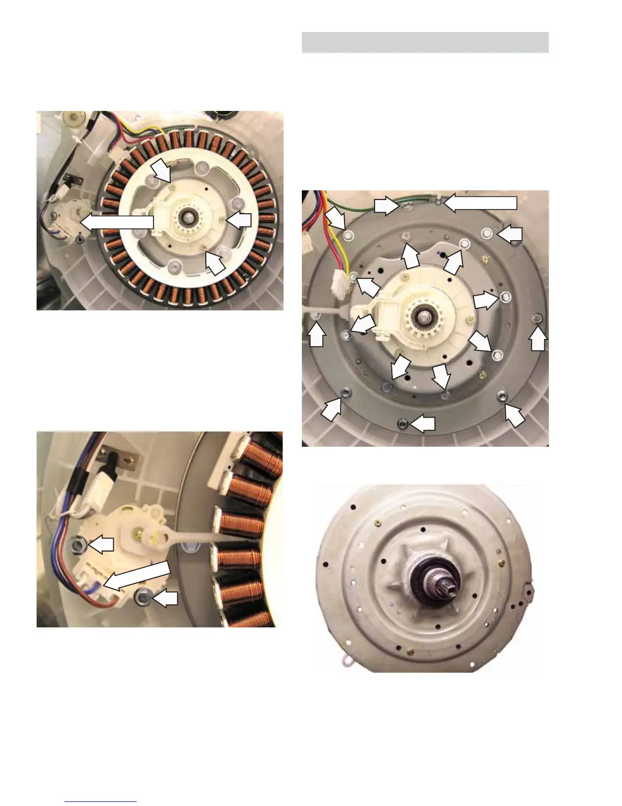
To remove the clutch shifter assembly:
Remove the rotor. (See 1.
Motor Assembly.)
Remove the three Phillips-head screws from the 2.
clutch coupler plate.
Disconnect
Bearing Housing Assembly
To remove the bearing housing assembly:
Remove the motor assembly and clutch shifter 1.
assembly. (See
Motor Assembly and Clutch Shifter
Assembly.)
Remove the screw that holds the ground wire 2.
to the bearing housing. Remove the sixteen 10-
mm hex-head screws from the bearing housing
assembly.
3. Remove the bearing housing assembly.
Ground Wire
Note: When reassembling, be sure to put the motor
and Hall sensor wires back in the wiring guard away
from the motor.
Clutch Motor
 Loading...