– 29 –
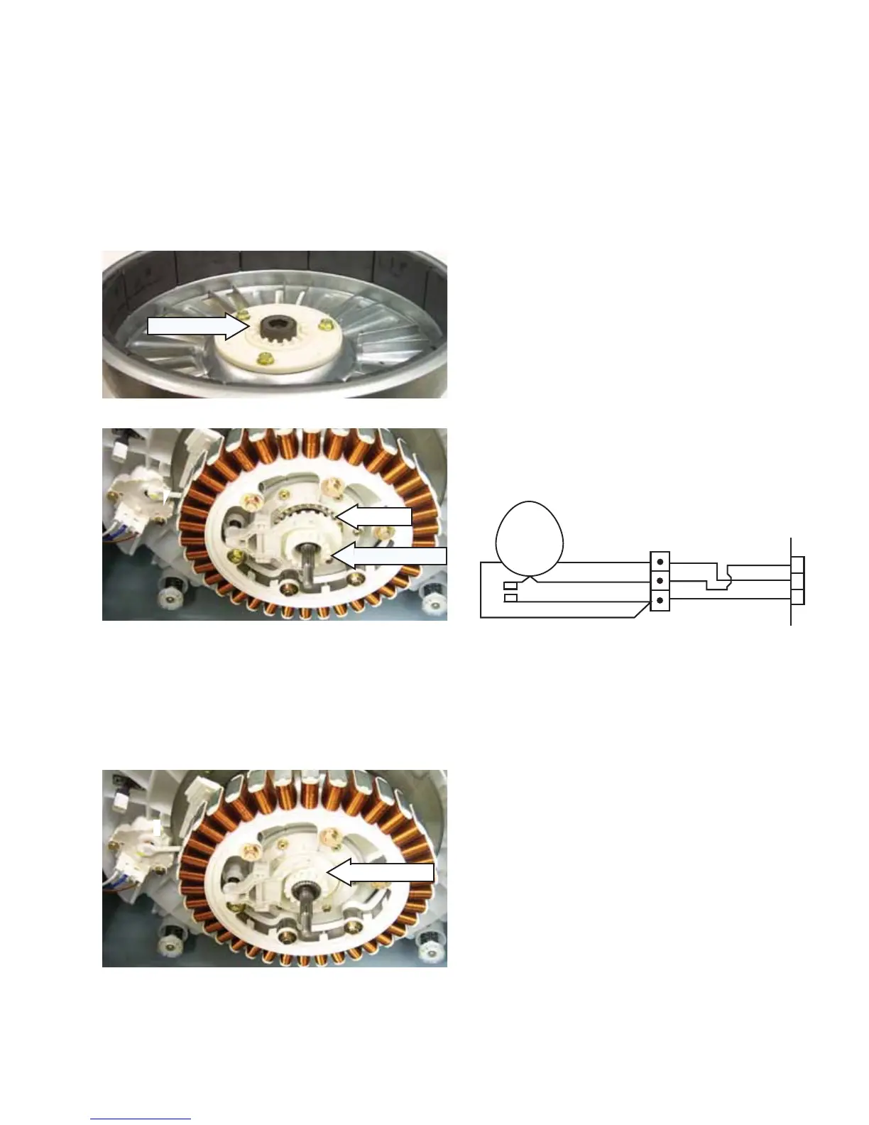
Clutch Operation
The clutch locks and unlocks the basket by •
engaging teeth on the inside of the rotor with
teeth on the clutch coupler.
When the basket and infusor are in the locked •
position, the clutch moves downward and
engages the rotor and clutch coupler teeth
allowing the basket to rotate with the infusor.
When the basket and infusor are in the unlocked •
position, the clutch moves upward, disengaging
the clutch coupler and rotor teeth, allowing the
infusor to rotate independently of the basket.
Unlocked
Locked
Clutch Coupler
Rotor Teeth
To diagnose the clutch motor:
The inverter supplies 120 VAC to the clutch •
motor through the brown and white wires when
the clutch motor changes position.
Note: Disconnect power and unplug the clutch
motor connector at the inverter board.
The clutch motor has an approximate resistance •
value of 2000
Ω. This can be measured
between the white and brown wires on the
inverter board. (See Inverter and Main Board Pin
Connectors.)
The rotation of the clutch motor causes an •
internal switch to open or close. This can be
measured between the brown and blue wires on
the inverter board.
When the clutch is in the unlocked position, the •
switch should be close
d (0
Ω
).
When the clutch is in the locked position, the •
switch should be open (infi nity).
(Continued Next Page)
Dk. Blue
White
Brown
1
2
3
White
Dk. Blue
Brown
CLUTCH
MOTOR
& CAM
 Loading...