– 43 –
7. Check upper and lower halogen lamp
operation at power level 10 and again at
power level 5 to be sure that lamps are cycling
properly. At this point, you must have a
thorough understanding of power level
operation, upper halogen lamp balance
operation, and thermal compensation (see
pages 17-21 of this service guide for detailed
information).
8. Confirm that thermal compensation is
operating properly by following the thermal
compensation test (see page 21 of this
service guide).
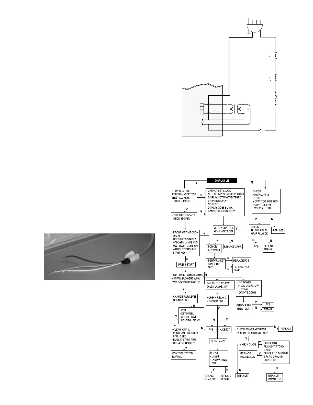
Diagnosing a “Dead” Unit
A “dead” unit is better defined as a unit that
appears to have no power to it (no clock display,
oven cavity lamp, or key panel responses). The
following components and associated wiring
should be checked in the below order when
diagnosing a “dead” unit.
1. At the power source, use your volt/ohmmeter
and check the resistance from L1 to
NEUTRAL. The resistance should be
approximately 22.0 ohms. Note: The
resistance reading that you just made is
shown in the schematic diagram at the upper
right corner of this page (low voltage
transformer primary resistance).
GEA00517
2. If you do not read continuity from L1 to
NEUTRAL, suspect the following:
• Open fuse
• Open cavity T.C.O.
• Low voltage transformer (open primary
winding)
• Open magnetron tube T.C.O.
• Open thermal fuse
• Defective smart board
Also, check all associated wiring and wiring
connections.
3. If you read approximately 22 ohms from L1 to
NEUTRAL, suspect a defective smart board,
loose wiring connection, or open secondary
winding of the low voltage transformer.
GEA00436
GEA00435
CN11
CN1
CAVITY T.C.O
ONE SHOT
(150/0 C)
(302/32 F)
M.G.T T.C.O
(150/60 C)
(302/140 F)
THERMAL FUSE
ONE SHOT
(195 C)
(383 F)
FUSE(20A)
AC 240V/60Hz
W
R
R
RR
R
VARISTOR
B
W
22.0
L.V.T
Y
B/B
B
R/B
L1L2N
SMART
BOARD




 To Next Page