– 32 –
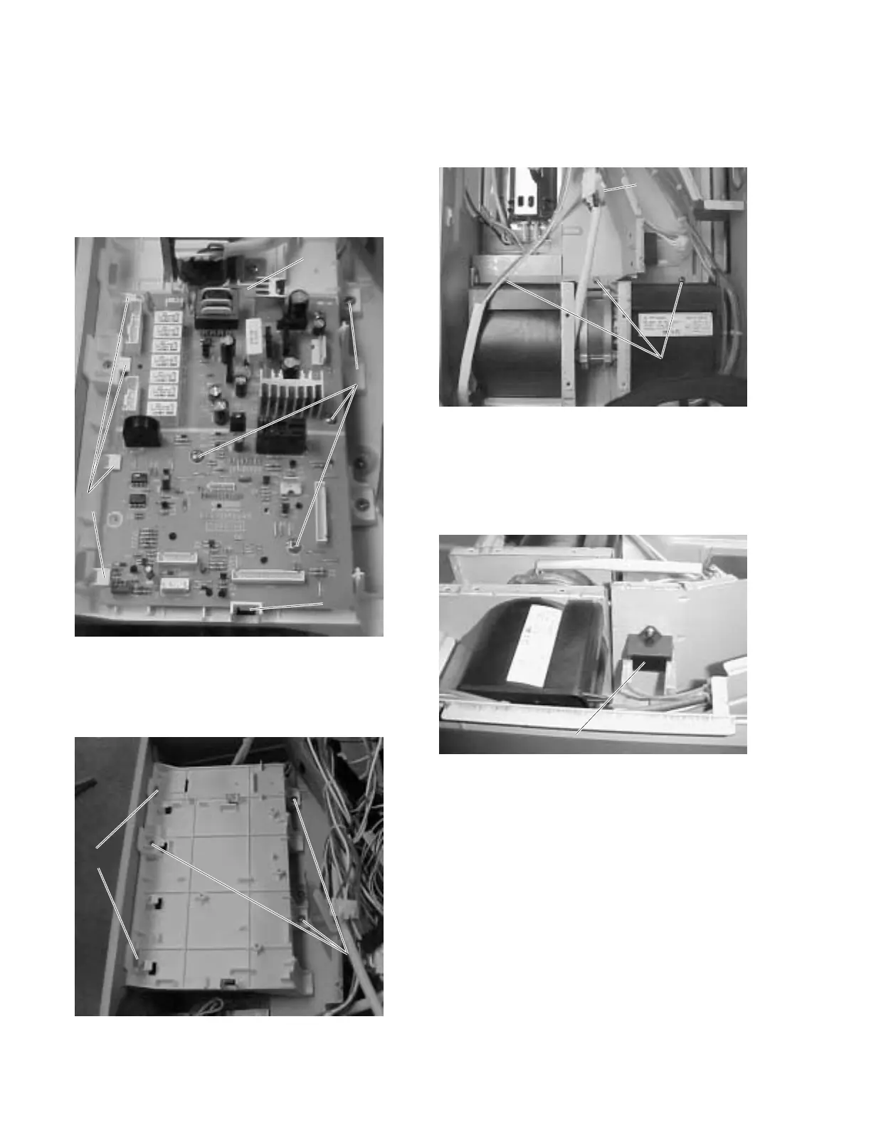
Remove Main PCB Assembly
1. Remove the top and rear access covers (see
pages 28-29).
2. Remove 4 screws that attach the main PCB
assembly to the plastic support.
3. Slide the board forward and lift it slightly
upward to disengage the board from 4 rear
tabs.
4. Remove 2 screws on the front and 1 screw on
the back of the plastic support. Slide the
support to the left.
Remove Upper Exhaust Assembly - Left
1. Remove the top, left, and rear access covers
(see pages 28-29).
2. Remove 3 screws and disconnect the harness.
GEA00452
ScrewsScrews
Harness
Disconnect
Harness
Disconnect
3. Lift exhaust motor upward to remove.
Note: The fan capacitor is located to the right of
the exhaust motor.
GEA00453
Fan CapacitorFan Capacitor
Remove Damper Door Assembly
1. Remove the top and right access covers (see
page 28).
GEA00450
ScrewsScrews
Rear TabsRear Tabs
TabsTabs
TabsTabs
GEA00451
ScrewsScrews
TabsTabs
 Loading...