GE
D
IRECTION GB091046, REVISION 2 VIVID E9 / VIVID E7 BT’13 SERVICE MANUAL
5 - 60 Section 5-9 - Back End Processor (BEP)
5-9-13 BEP Power Supply
5-9-13-1 Description
• BEP6.0 Power Board Assembly
NOTE: The BEP Power Supply does not handle AC voltages.
The BEP Power Supply receives its input DC voltage from the VIVID E9 / VIVID E7’s Main Power
Supply.
Dedicated control signals, are used for controlling the BEP Power Supply.
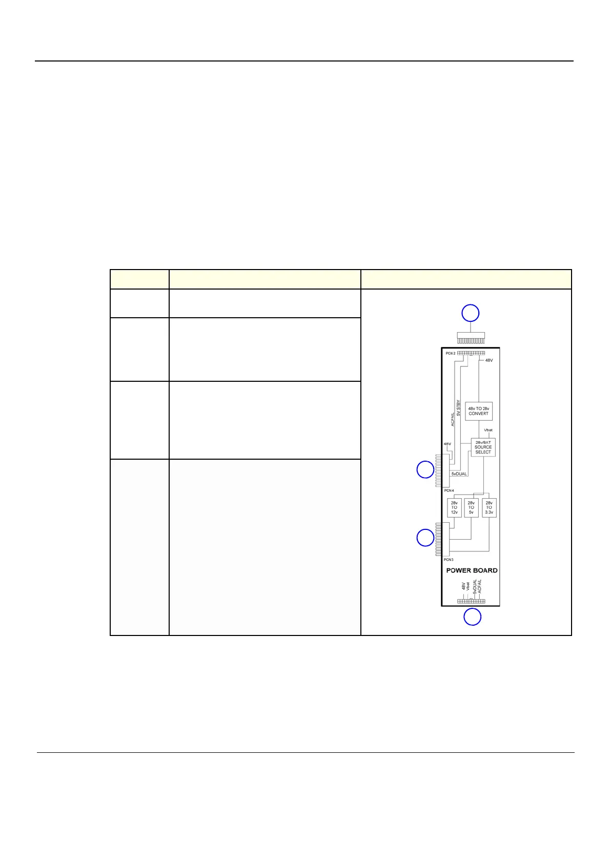
5-9-13-2 BEP6 Power Board Assembly Block Diagram
5-9-13-3 Location in the BEP6
The BEP6 Power Supply Card is located inside the BEP6, at the right-hand side (when opening the
BEP).
Table 5-17 BEP6 Power Supply Block Diagram
ITEM DESCRIPTION ILLUSTRATION
1.
This connector is not used in the VIVID E9 /
VIVID E7.
2.
PCN 2
• +48 VDC from Main Power Supply > “POWER
CABLE – BEP 48V” (GA200715) > connector J1
(on top of BEP6) > PCN 2.
• Control signals: ACFAIL and 5V STBY.
3.
PCN 3
This plug fits into the connector CN PWR2 on the
BEP6’s motherboard.
• +12 VDC to the BEP6 motherboard.
• + 5VDC to the BEP6 motherboard.
• +3.3VDC to the BEP6 motherboard.
4.
PCN 4
This plug fits into the connector CN PWR1 on the
BEP6’s motherboard.
• +48 VDC to the BEP6 motherboard.
• Control signals: ACFAIL, 5V STBY and 5vDUAL