GE
D
IRECTION GB091046, REVISION 2 VIVID E9 / VIVID E7 BT’13 SERVICE MANUAL
8 - 114 Section 8-6 - Top Console Parts Replacement Overview
8-6-16 Replacing the Trackball
8-6-16-1 Preparations
When preparing for the replacement, you must perform the following steps:
1.) Power down the VIVID E9 / VIVID E7.
2.) Disconnect the Mains Power Cable from the wall outlet.
3.) Disconnect all probes and external I/O cabling.
4.) Remove the Operator Panel, Upper.
5.) Remove the Operator Panel, Lower and place it on a clean surface with the front down.
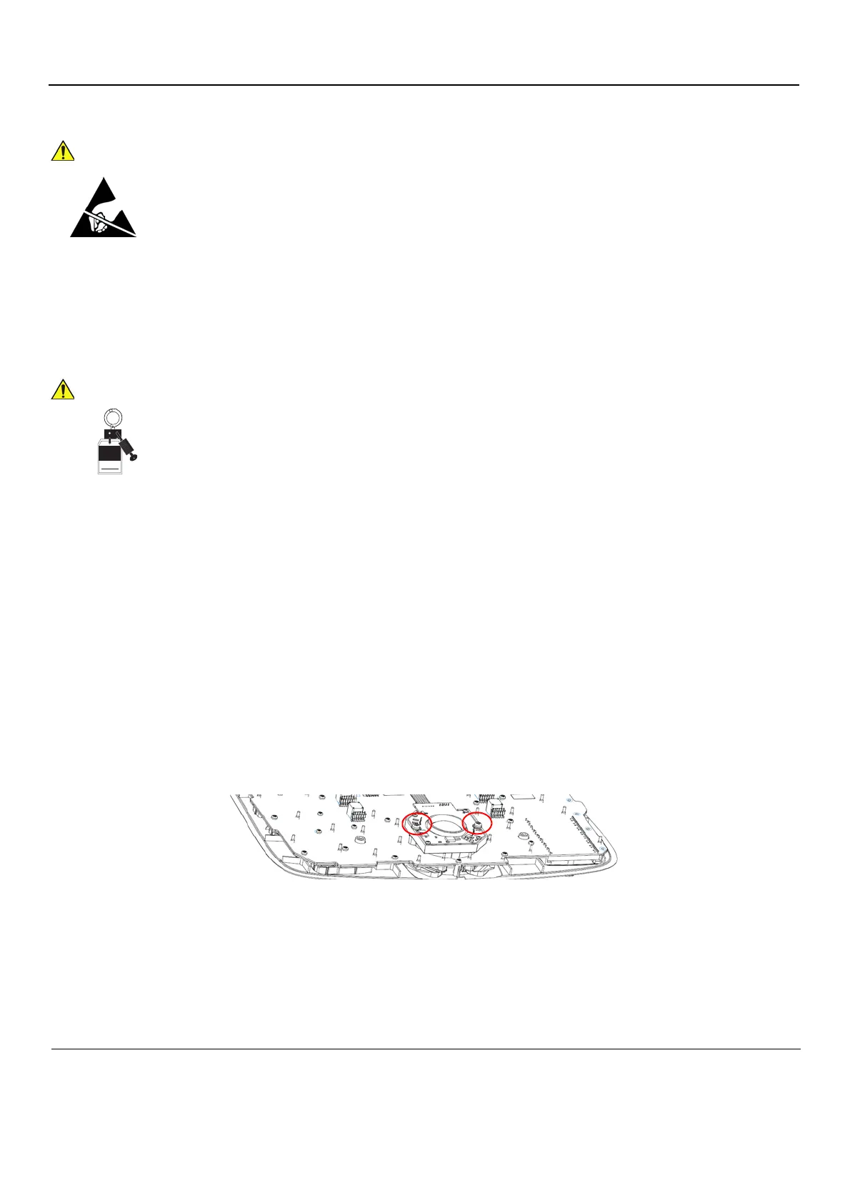
8-6-16-2 Remove the Trackball
Follow these steps to remove the Trackball:
1.) Unplug the cable connectors from the Trackball.
2.) Use the Hex key to remove the two fixing screws with washers.
3.) Remove the Trackball and the Fixing Ring.
DO NOT TOUCH ANY BOARDS WITH INTEGRATED CIRCUITS PRIOR TO TAKING THE
NECESSARY ESD PRECAUTIONS.
1. ALWAYS CONNECT YOURSELF, VIA AN ARM-WRIST STRAP, TO THE ADVISED
ESD CONNECTION POINT LOCATED ON THE REAR OF THE SCANNER (NEAR THE
POWER CONNECTOR).
2. FOLLOW GENERAL GUIDELINES FOR HANDLING OF ELECTROSTATIC SENSITIVE
EQUIPMENT.
ENERGY CONTROL AND POWER LOCKOUT FOR VIVID E9 / VIVID E7.
WHEN SERVICING PARTS OF THE SYSTEM WHERE THERE IS EXPOSURE TO
VOLTAGE GREATER THAN 30 VOLTS:
1. FOLLOW LOCK OUT/TAG OUT PROCEDURES.
2. TURN OFF THE BREAKER.
3. UNPLUG THE VIVID E9 / VIVID E7.
4. MAINTAIN CONTROL OF THE POWER PLUG.
5. WAIT FOR AT LEAST 20 SECONDS FOR CAPACITORS TO DISCHARGE, AS THERE ARE NO TEST POINTS TO
VERIFY ISOLATION. THE AMBER LIGHT ON THE OP PANEL ON/OFF BUTTON WILL TURN OFF.
BEWARE THAT THE MAIN POWER SUPPLY AND BACK END PROCESSOR MAY BE ENERGIZED EVEN IF THE POWER
IS TURNED OFF WHEN THE CORD IS STILL PLUGGED INTO THE AC OUTLET.
Figure 8-103 Trackball with fixing screws