GE
D
IRECTION GB091046, REVISION 2 VIVID E9 / VIVID E7 BT’13 SERVICE MANUAL
8 - 164 Section 8-7 - Replacing XYZ Parts
8-7-2-2 XY-Brake Assy removal procedure
The four (4x) XY-Brake Assemblies are located inside the XY (froglegs), one in each leg.
To remove one XY-Brake ASSY, follow these steps:
1.) Unscrew and remove the screw(s) that fix the cover to the leg.
2.) Remove the cover.
3.) Disconnect the XY Brake cable.
4.) Unscrew and remove the fixing screw for the XY Brake Assy.
5.) Remove the brake retainer screw.
6.) Disconnect the brake motor wire connector.
7.) Using a 3 mm, “L” Allen wrench, slide the short “L” end of the wrench between the motor and the
metal part of the brake ramp. The short “L“-end, should be visible as shown in Figure 8-145.
BE CAREFUL not to pinch the brake motor wires.See: Figure 8-146 "XY Brake Allen wrench
placement - reference" on page 8-165.
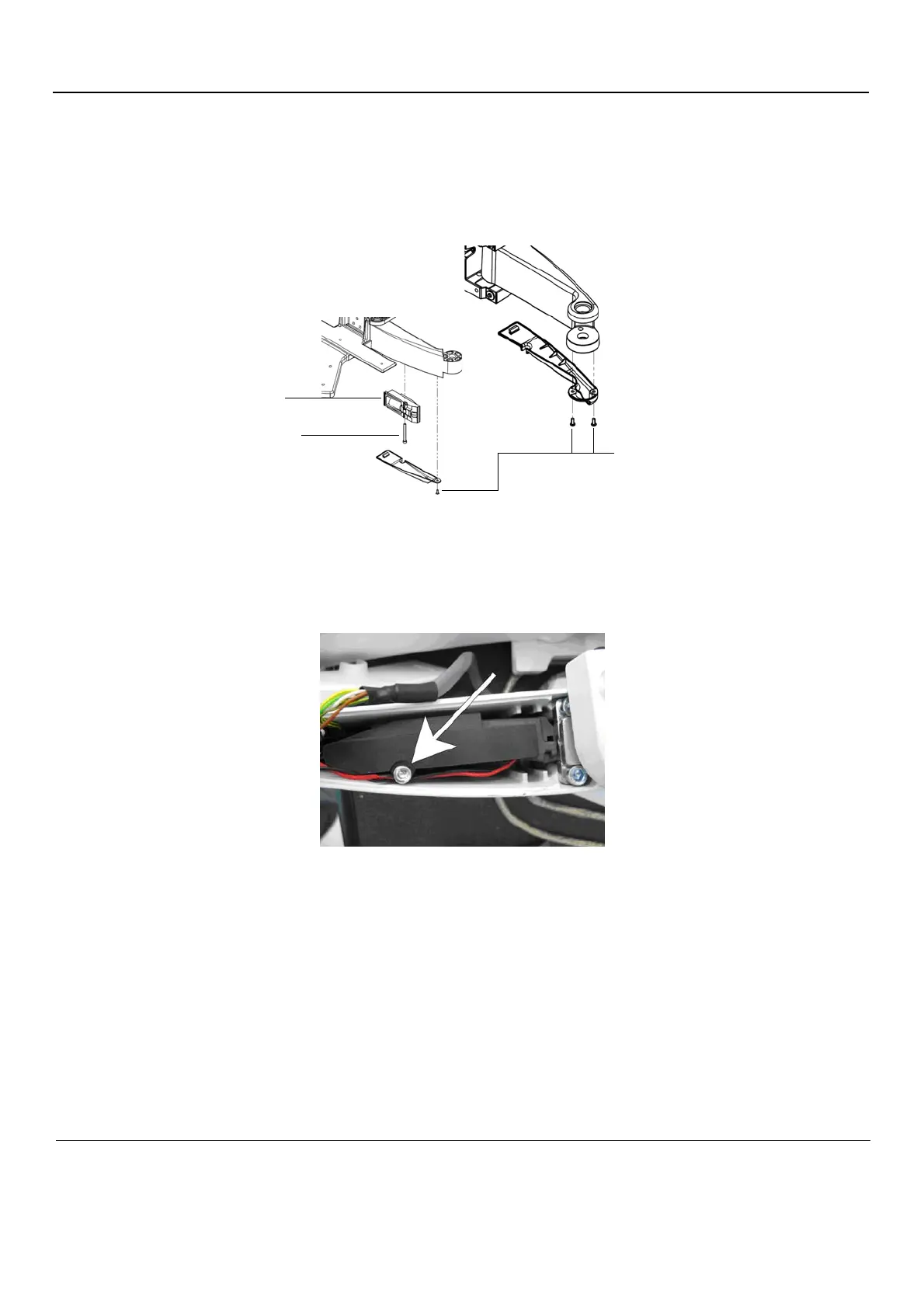
Figure 8-143 Covers, XY Brake ASSY and fixing screws
Figure 8-144 XY Brake Retaining Screw
FIXING SCREWS FOR
XY BRAKE ASSY
XY BRAKE ASSY
FIXING SCREWS
FOR COVERS