GE
D
IRECTION GB091046, REVISION 2 VIVID E9 / VIVID E7 BT’13 SERVICE MANUAL
10 - 20 Section 10-6 - Electrical Safety Tests
10-6-4-2 Generic Procedure
The test verifies the isolation of the power line from the chassis.
The testing meter is connected from accessible metal parts of the case to ground.
Measurements should be made under the test conditions specified in:
• Table 10-8 on page 10-16,
or:
• Table 10-9 on page 10-17,
as applicable.
Record the highest reading of current.
1.) Connect Safety analyzer to wall AC power outlet.
2.) Plug the equipment under test power cable into the receptacle on the panel of the meter.
3.) Connect the meter to an accessible metal surface of the scanner using the cable provided with the
meter.
.
4.) Select the Chassis or Enclosure leakage function on the meter.
NOTE: For more information, refer to the safety analyzer's user manual.
5.) Test opening and closing the ground with the scanner on and off as indicated in:
• Table 10-8 on page 10-16,
or:
• Table 10-9 on page 10-17,
as applicable.
The maximum allowable limit for chassis source leakage is also shown in:
• Table 10-8 on page 10-16, or
• Table 10-9 on page 10-17,
as Chassis/Enclosure Leakage.
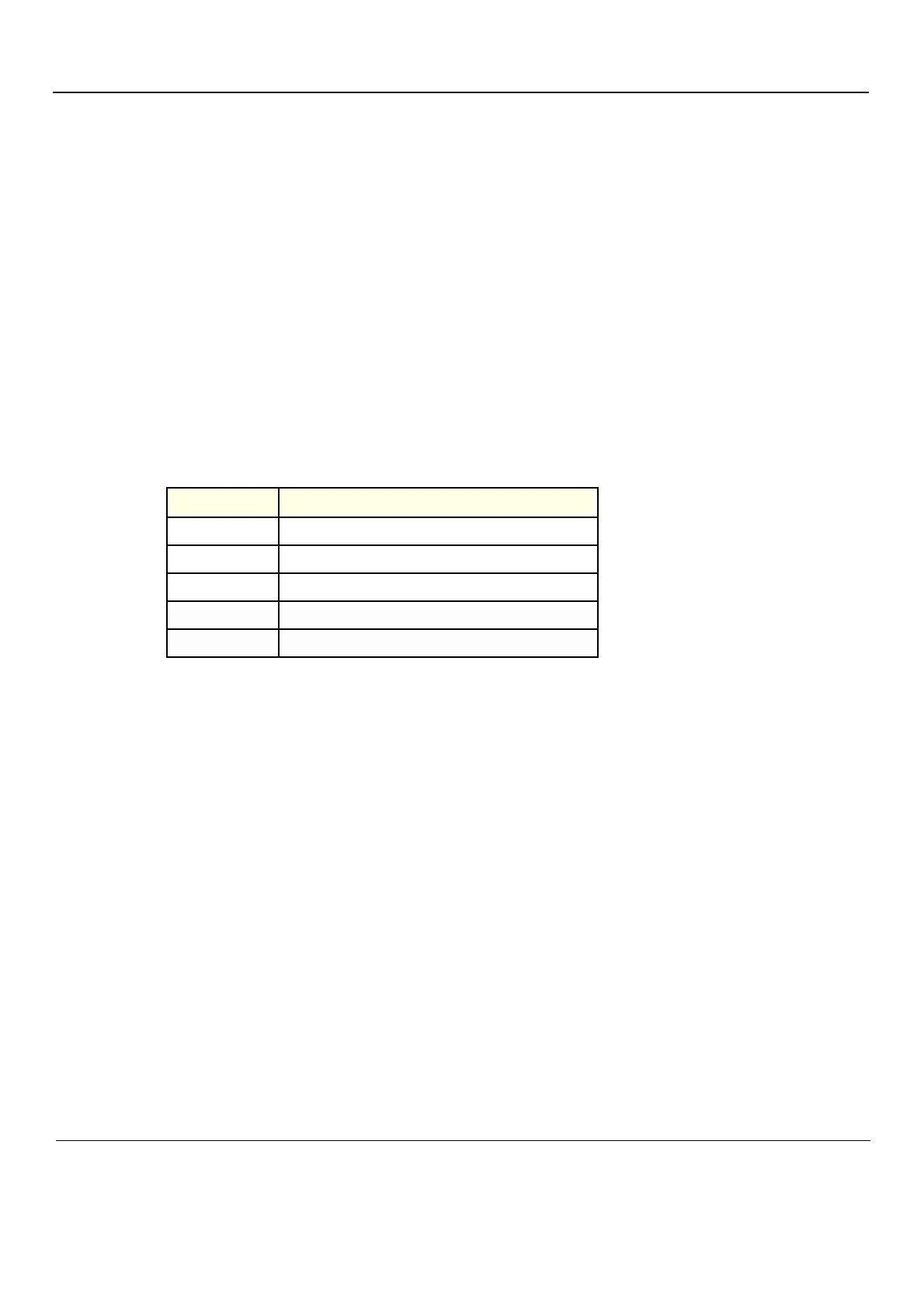
Table 10-12 Chassis leakage current test locations
TEST CONDITION
1
Mounting screw for probe receptacle
2
Wheel support
3
Mounting screw for LCD or CRT housing
4
Mounting screw for peripheral plugged into unit
5
Mounting screw for other peripheral powered by unit