EasyManuals Logo

GE Vivid E95 User Manual

GE Vivid E95
382 pages
To Next Page IconTo Next Page
To Previous Page IconTo Previous Page
Page #195 background imageLoading...
Page #195 background image
Back End Processor (BEP)
Vivid E80/E90/E95 – Service Manual 5-35
GC091052 Rev. 3
Outside the EMC enclosure house
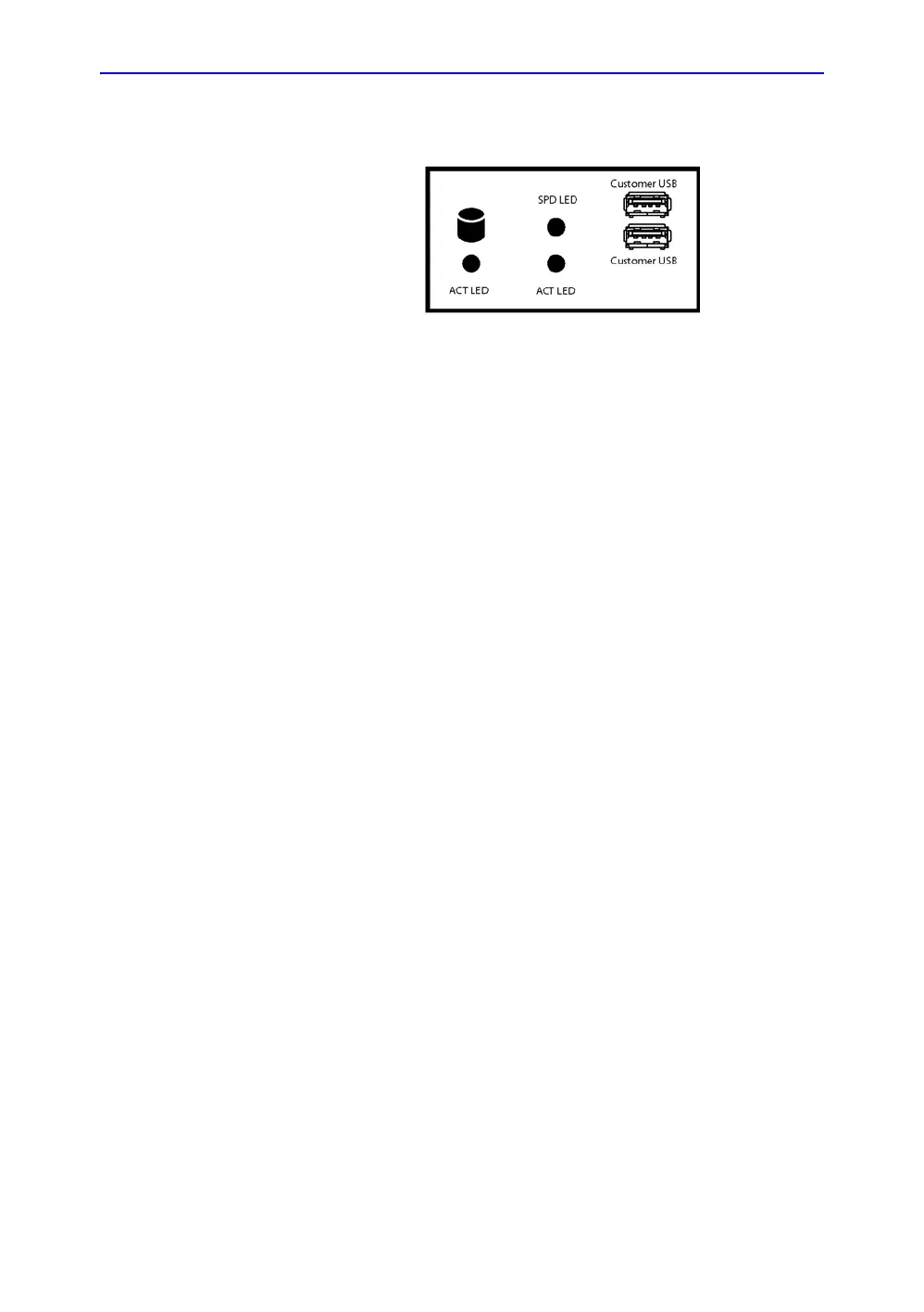
Figure 5-18. BEP Front Panel
• Front Panel with:
• status light (LED) for hard disk activity
• status lights (LEDs) network speed (upper LED) and
network activity (lower LED)
• two USB ports
• Patient I/O with AUX, Phono and ECG connectors
• BEP I/O board (available from the BEP’s outside)
BEP’s side connectors
Connectors on the BEP’s side:
• J21: Upper LCD Video Out
• J6: Digital Audio Out
• J22: A/V Out
• Test Connector
• J7: USB - Operating Panel buttons
• J28: USB - XYZ Motor Controller
• Spare USB
• J26:USB - BW printer
• Spare USB
• J4: USB - Main Power Supply
• Spare USB
• Spare USB
• J3: SATA1 - DVD
• J2: SATA - Spare

Table of Contents

Other manuals for GE Vivid E95

Questions and Answers:

Question and Answer IconNeed help?

Do you have a question about the GE Vivid E95 and is the answer not in the manual?

GE Vivid E95 Specifications

General IconGeneral
TypeCardiovascular Ultrasound System
Transducers2D, 3D, 4D
Display22-inch high-resolution OLED monitor
PortabilityCart-based
Imaging Modes2D, 3D, 4D, Color Doppler
Advanced FeaturescSound Architecture
ConnectivityDICOM, USB, Ethernet
ApplicationsCardiology, Vascular, Abdominal

Related product manuals