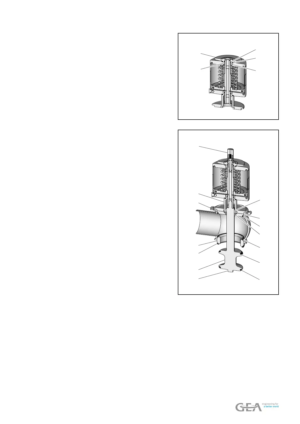
4. Equip the installation base (198.2)
with
O-rings (98, 99) and slide bear-
ings (202) and position in the installa-
tion base (198.1).
5. Screw the installation base unit into
the actuator using the articulated face
spanner, and tighten.
®
Observe torques, see table ‘Tight-
ening torques’.
9.6.1 Tightening
torques
.
6. Press the bearing (2) into the lantern
(9).
7. Place
the seal disk (3) with the O-ring
(5) and seal ring (1) into the housing.
8. Place the lantern (9) onto the housing
and mount the hinged clamp (43) be-
tween the housing and the lantern.
®
Observe torques, see table ‘Tight-
ening torques’.
9.6.1 Tightening
torques
.
9. Place the seat ring (33) with the O-
ring (5) into the housing.
10. Screw valve disk (15) with the V-ring
(7) into actuator and tighten using
jaw wrench at wrench at surface
(15.1). To do this, afx with a belt
wrench.
®
Observe torques, see table ‘Tight-
ening torques’.
9.6.1 Tightening
torques
.
11. Screw the switch bar (1) into the actuator using a jaw wrench.
Þ
The valve insert is assembled fr
om individual parts.
9.6 Installing the valve - 79 / 128





 To Next Page