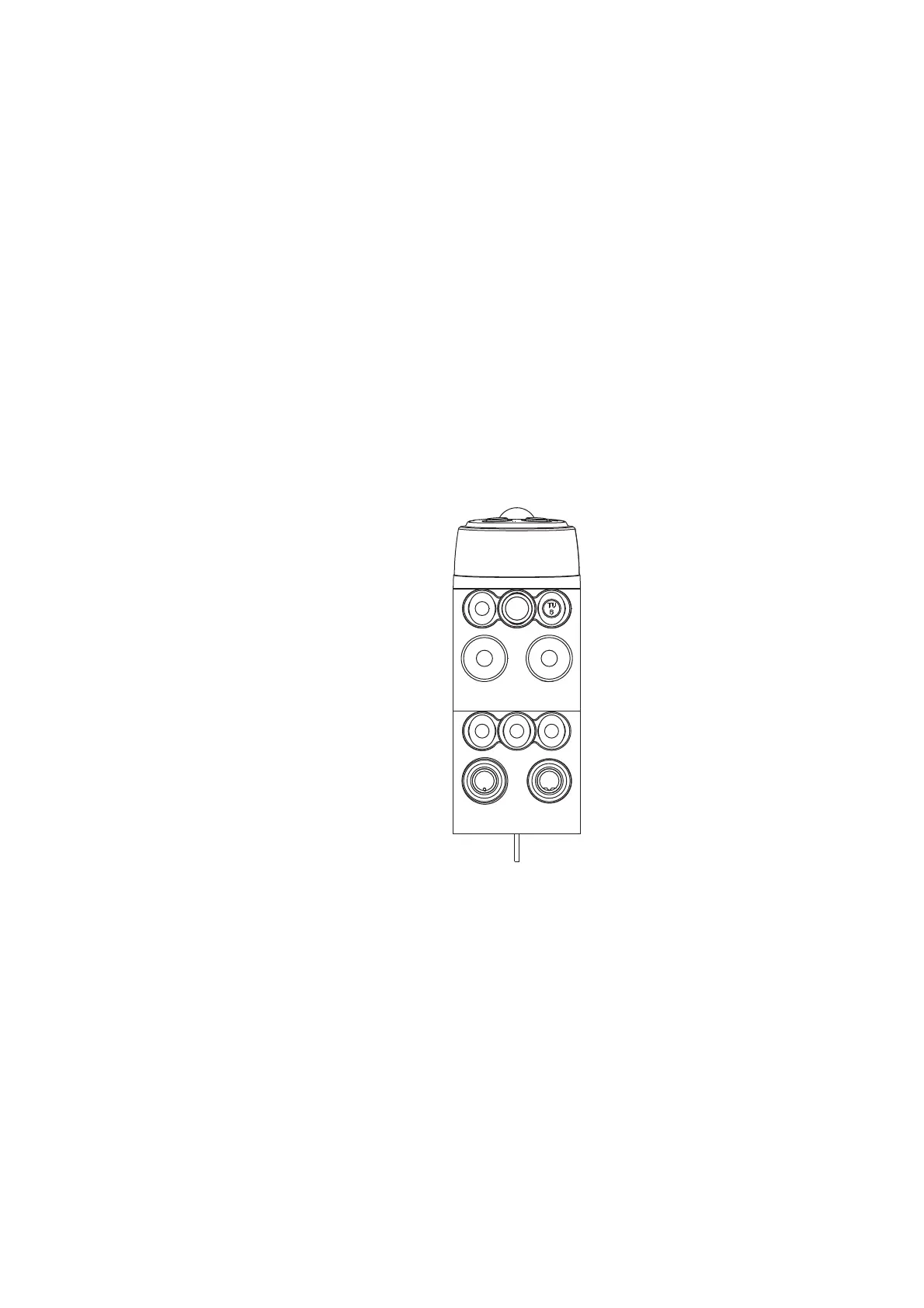
Aufsatz 1
1 Elektrischer Anschluss
mit M12 Steckdose,
A-codiert
2 Elektrischer Anschluss
mit M12 Steckdose,
B-codiert
E Schlauchverbindung zu
Aufsatz 2 E
Y Steuerluft-Anschluss
für VESTA-Antrieb
P Zentrale Luftversor-
gung
Aufsatz 2
1 Mit Blindkappe
verschlossen
2 Mit Blindkappe
verschlossen .
E Schlauchverbindung zu
Aufsatz 1 E
Y Abluft-Anschluss für
Schalldämpfer
P Blindstopfen
Aufsatz 2/
Base element 2
Aufsatz 1/
Base element 1
Pneumatischer Anschluss
Luftschlauch montieren
✗Für einen optimalen Sitz im Luftanschluss, ist es
notwendig, die Pneumatikschläuche mit einem
Schlauchschneider rechtwinklig zu schneiden.
• Druckluftversorgung abstellen.
• Luftschlauch in den Luftanschluss Aufsatz 1,
Anschluss P des Anschlusskopfes schieben.
• Druckluftversorgung wieder freigeben.
Anschlussbild
Base element 1
1 Electrical connection
with M12 socket,
A-coded
2 Electrical connection
with M12 socket,
B-coded
E Hose connection to
attachment E
Y Control air connection
for VESTA actuator
P Central air supply
Base element 2
1 Sealed with blind cap
2 Sealed with blind cap
E Hose connection to
attachment 1 E
Y Exhaust air connection
for sound absorber
P Blind plug
Pneumatic Connections
Installing the air hose
✗To ensure optimum seat in the air connector, the
pneumatic hoses must be cut square with a hose
cutter.
• Shut-off the compressed air supply.
• Push the air hose into the air connector Base element
1, connection P of the control module.
• Re-open the compressed air supply.
Connection picture
 Loading...