21
2013-10 · Anschlusskopf T.VIS P-1 / Control Module T.VIS
®
P-1
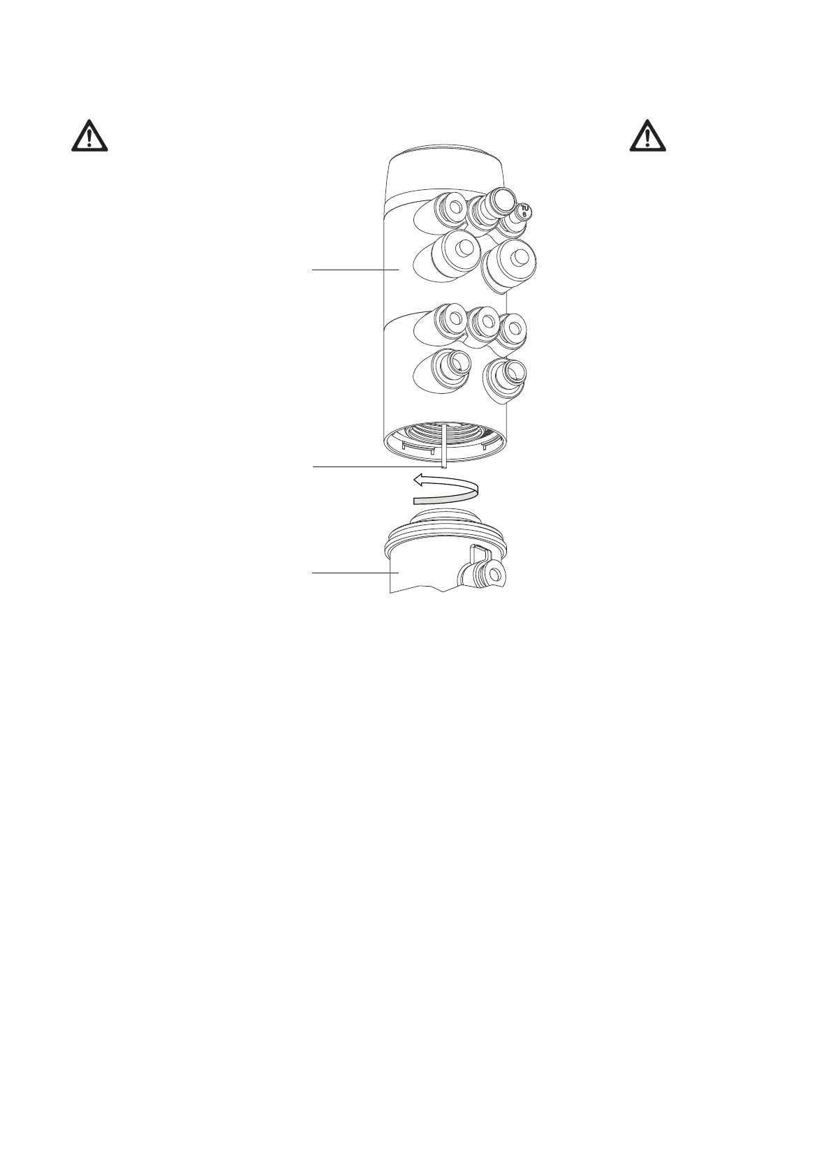
Montage
VORSICHT
Die Potentiometerspindel
(P) ist ein empfindliches
Bauteil und muss vorsich-
tig behandelt werden!
• Potentiometerspindel
(P) vorsichtig in den
Ventileinsatz (A) einfüh-
ren.
• Stellungsregler (B) nach
rechts (in Pfeilrichtung),
bis zum Anschlag, auf
den Ventileinsatz (A)
aufschrauben und
handfest festdrehen
(max. Drehmoment
3 Nm).
• Die Anschlüsse durch
Zurückdrehen des Stel-
lungsreglers (B) ausrich-
ten (innerhalb der hör-
baren Einrastungen,
aber max. 350°).
Assembly
CAUTION
The potentiometer
spindle (P) is a sensitive
component and must be
handled with care!
• Carefully insert poten-
tiometer spindle (P) into
the valve insert (A).
• Screw positioner (B)
onto the valve insert (A)
by turning it to the right
(in direction of the
arrow) up to the limit
stop; fasten hand-tight
(torque 3Nm max. ).
• Align connection ports
by turning the
positioner (B) (while
audibly engaging, but
max 350°).
B
P
A

 Loading...