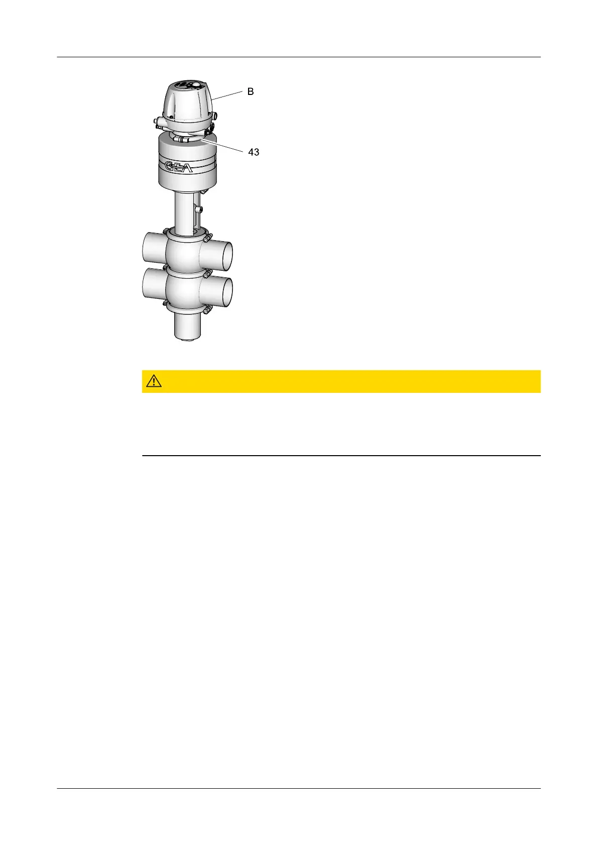
Fig.18
Caution!
The switch bar is sensitive and must be protected from impact
stress.
Damage to switch bar.
► Protect the switch bar against impact stress.
Carry out the following steps:
1.
Put on the control top (B) from the top.
2.
Attach the pneumatic connection from the actuator.
3.
Remove the clamp connection (43) from the control top (B).
! Ensure that the clamp connections (43) are firmly installed.
®
Done
10.6.4 Assembly of the housing combination
If a housing combination is loose, mount it.
Carry out the following steps:
1.
Insert the seating ring between the housings so that the arrow later properly
displays the direction of the drive when the valve is completely assembled!
The seating ring should be placed with the arrow pointing to the displayed
installation direction.
Maintenance
Installation
430BAL008386EN_3
07.02.2022 49
 Loading...