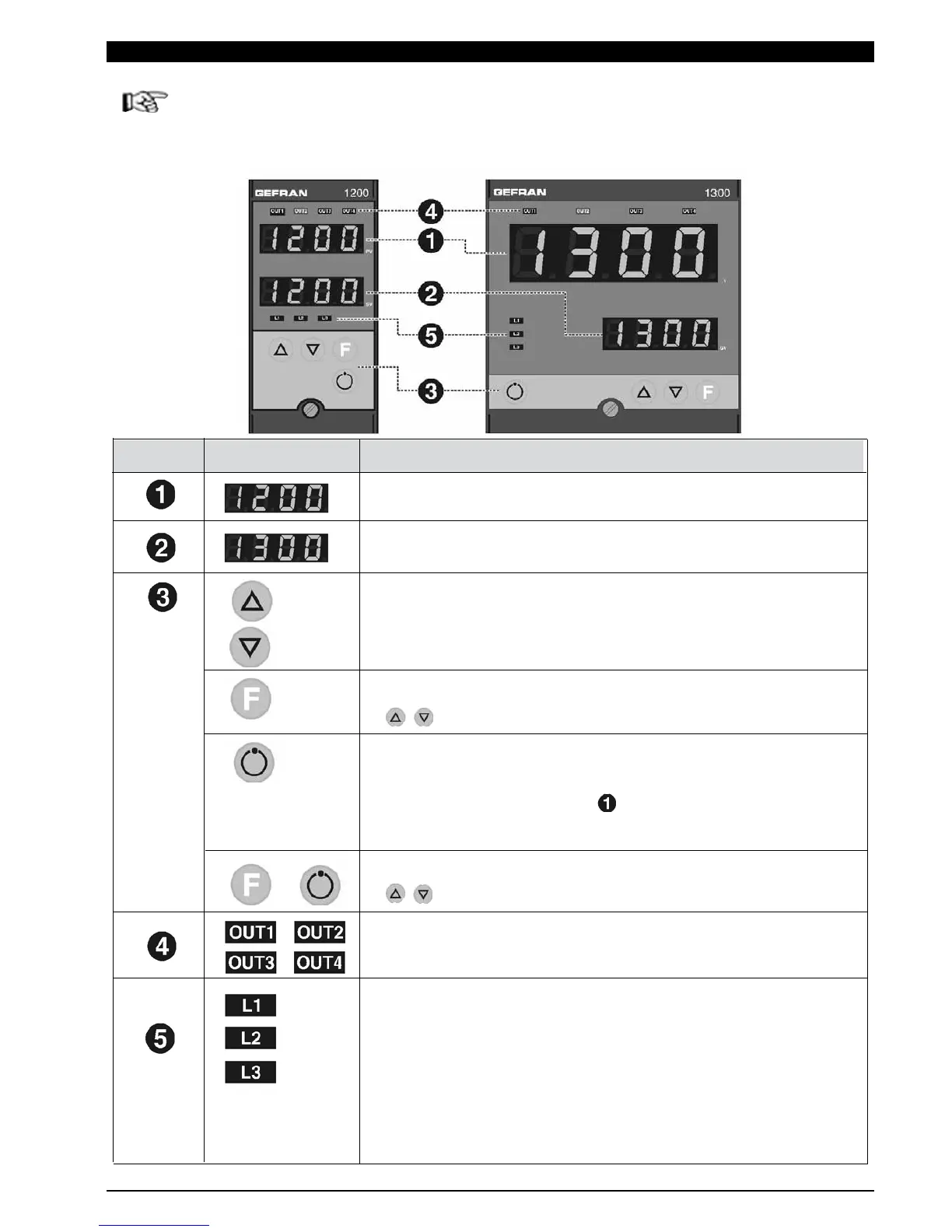
PV : Shows the process variable, the menu identification, the
parameters identification and the error codes
SV : Shows the setpoint value, the value of the parameter displayed in
PV and three dashes (- - -) when PV contains a menu heading
Increases/Decreases the value of the parameter displayed in SV until
the max/min. value is reached.
Held down: progressively increases the speed of increasing/decreasing
the value displayed in SV.
Used to move between the various menus and parameters of the controller.
Confirms the value of the current parameter (or parameter edited using
) and selects the next parameter.
Button with configurable function: with standard configuration commutes the
controller operating mode (MANUAL/AUTOMATIC).
Is only on when the display shows the process variable.
(for configuration see parameter BVT in the KRD menu)
Confirms the value of the current parameter (or parameter edited using
) and selects the previous parameter.
Output status indicators:
OUT1 (AL1), OUT2 (Main), OUT3 (HB), OUT4
Function indicators: with standard configuration they show the controller
operating status
For configuration see parameter LD.1, LD.2, LD.3 in the KRD menu
L1 MAN/AUTO = OFF (automatic control)
ON (manual control)
L2 SETPOINT 1/2 = OFF (IN1= OFF local Setpoint 1)
ON (IN1=ON local Setpoint 2)
L3 SELFTUNING = ON (Self activated)
OFF(Self deactivated)
3 • FUNCTIONS
This section illustrates the functions and operating modes of the displays, the indicator lights and the
buttons that make up the operator interface of series 1200/1300 controllers. It is therefore an essential
requirement for programming and configuring the controllers correctly.
Operator Interface
ID Symbol Function
+
10
81801G_MHW_1200-1300_07-2011_ENG