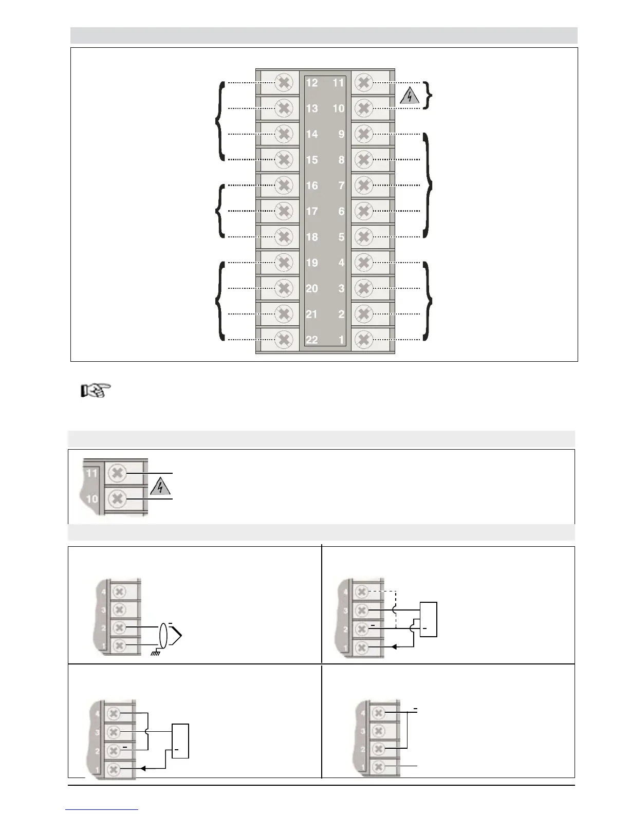
Electrical Connections
PWR
Outputs
Out1 - Out2
Inputs
Serial line
Digital inputs
/
CT Input
Outputs
Out3 - Out4
1200
Always make the connections using cable types suitable for the voltage and current limits given in
Section 5 - Technical Specifications.
If the Controller has faston terminals these must be protected and isolated.
If it has screw terminals, the wires must be attached, at least in pairs
Power Supply
Inputs
+
24V
4..20mA
VT
+
+
+
S
24VVT
+
+
+
+
Standard: 100...240Vac/dc ±10% , max 18VA
Optional: 11...27Vac/dc ±10% , max 11VA
50/60 Hz
Available thermocouples:
J, K, R, S, T
(B,E, N, L, U, G, D, C
possible by inserting a
custom linearization)
- Observe polarities
- For extensions, use the
correct compensating cable
for the type of TC used
Connect for 0/4..20mA
input
Jumper S3 closed on CPU
board
(see CAP. 6 Maintenance)
Linear input in
Direct Current
0/4..20mA, Ri = 50W
TC Input Linear input with 3-wire transmitter supplied from
the instrument
Linear input with 2-wire Transmitter supplied
from the instrument
Linear input (I)