PV
SV
L.
A
i
n
PV
SV
i
d
0
G
PV
SV
i
d
0
2
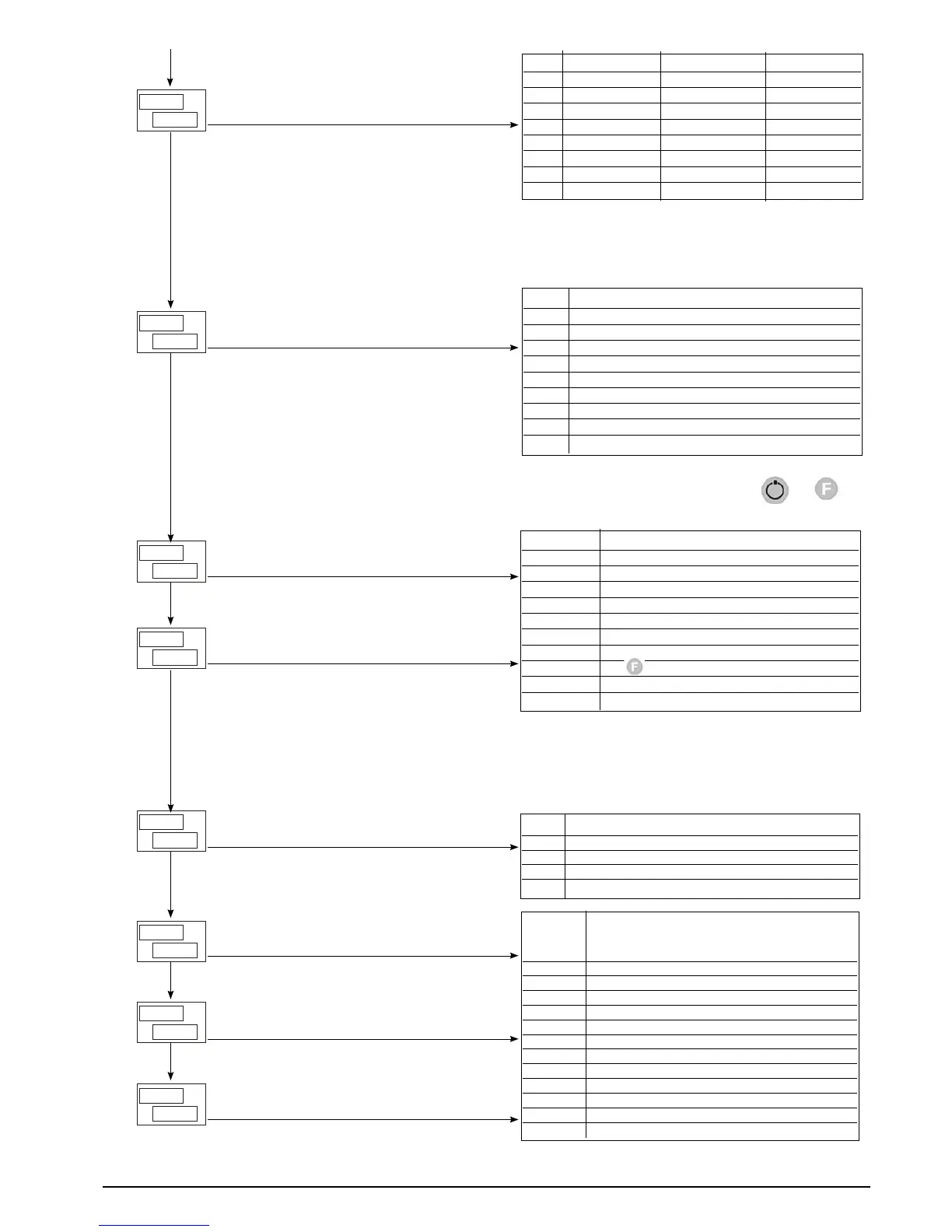
Function of digital input 1 (0 ... 53)
Function of digital input 2 (0 ... 53)
PV
SV
n
b
0
t
PV
SV
S
d
0
P
PV
SV
L
1
d.1
Function of led 1
Defining SV display function
Function of M/A key
PV
SV
L
20
d.3
Function of led 3
PV
SV
L
10
d.2
Function of led 2
Select number of enabled alarms
KRD
AL.N Alarm 1 Alarm 2 Alarm 3
0 disabled disabled disabled
1 enabled disabled disabled
2 disabled enabled disabled
3 enabled enabled disabled
4 disabled disabled enabled
5 enabled disabled enabled
6 disabled enabled enabled
7 enabled enabled enabled
By adding the following figures to the value in the table it is
possible to enable a series of supplementary functions:
+8: to enable HB alarm
+16: to enable LBA alarm
BVT Function
0 Key disabled (no function)
1 MAN / AUTO controller
2 LOC / REM
3 HOLD
4 Alarms memory reset
5 Select SP1 / SP2
6 Start / Stop Self Tuning
7 Start / Stop Auto Tuning
8 Set / Reset outputs OUT 1 ... OUT 4
By adding +16 to the value in the table, the “back menu”
function is disabled (keys combination + )
D ,G; D ,2 Function
0 Key disabled (no function)
1 MAN / AUTO controller
2 LOC / REM
3 HOLD
4 Alarms memory reset
5 Select SP1 / SP2
6 Software on/off
7 key block
8 Start / Stop Self Tuning
9 Start / Stop Auto Tuning
By adding the following figures to the value in the table it is
possible to enable a series of supplementary functions:
+16: for inverse logic input (NPN)
+32: to force logic state 0 (OFF)
+48: to force logic state 1 (ON)
DSP Function
0 SSP – setpoint enabled
1 InP.2 – auxiliary input
2 Control output value
3 Deviation (SSP – PV)
LD. 1
LD.2 Function
LD.3
0 No function
1 MAN / AUTO controller
2 LOC / REM
3 HOLD
4 Self Tuning enabled
5 Auto Tuning enabled
6 IN 1 repetition
7 Enable serial communication
8 Error
9 Softstart running
10 SP1 ... SP2 indication
11 Set point gradient running
By adding +16 to the value in the table, the LED flashes if
active
28
81801G_MHW_1200-1300_07-2011_ENG