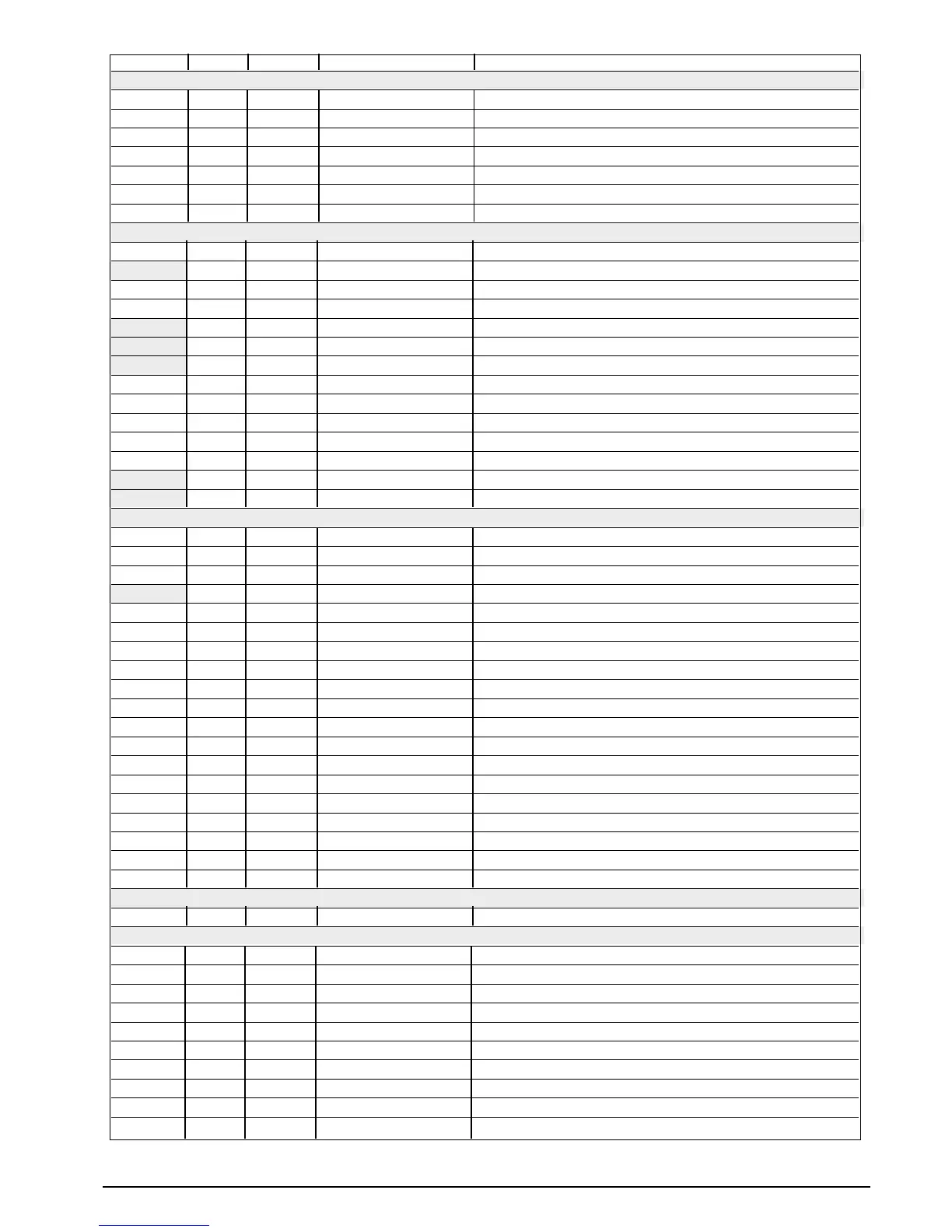
Display Default CONF Acronym Description
Menu SER
(OD 1 Instrument Code Instrument identification code
SR.P 1 Serial Protocol Serial interface protocol
BAV 4 bAudrate Baudrate selection
PAR 0 PArity Parity selection
S.IN 0 S. Input Virtual instrument inputs
S.0V 0 S. Output Virtual instrument outputs
S.UI 0 S. User Interface Virtual instrument user interface
Menu INP
SP.R 0 SetPoint remote Remote Setpoint
TYP 0 type of Probe Type of probe, signal, Linearization enabling etc.
FLT 0.1 FiLter Digital filter on input
FLD 0.5 FiLter display Digital filter on display
DP.S 0 dot Position Scale Decimal point position for input scale
LO.S 0 Low Scale Minimum limit main input scale
Ki.S 1000 High Scale Maximum limit main input scale
OFS 0 oFfSet Offset correction of main input
FT.2 0.1 Filter 2 Auxiliary input digital filter
LS.2 0.0 Limit Scale 2 Minimum limit auxiliary input scale
KS.2 100.0 High Scale 2 Maximum limit auxiliary input scale
0F.2 0.0 OFfset 2 Offset correction of auxiliary input
LO.L 0 Low Limit Lower limit for setting SP and absolute alarms
Ki.L 1000 High Limit Upper limit for setting SP and absolute alarms
Menu 0VT
A1.R 0 Alarm 1 reference Select reference value for alarm 1
A2.R 0 Alarm 2 reference Select reference value for alarm 2
A3.R 0 Alarm 3 reference Select reference value for alarm 3
A1.T 0 Alarm 1 type Alarm 1 type
A2.T 0 Alarm 2 type Alarm 2 type
A3.T 0 Alarm 3 type Alarm 3 type
KB.F 4 Hb Function HB alarm functions
RL.1 2 reference Line 1 OUT 1 Reference signal allocation
RL.2 0 reference Line 2 OUT 2 Reference signal allocation
RL.3 3 reference Line 3 OUT 3 Reference signal allocation
RL.4 4 reference Line 4 OUT 4 Reference signal allocation
(T.1 20 Cycle time 1 OUT 1 cycle time (+HEAT/-COOL)
(T.2 20 Cycle time 2 OUT 2 cycle time (+HEAT/-COOL)
(T.3 20 Cycle time 3 OUT 3 cycle time (+HEAT/-COOL)
(T.4 20 Cycle time 4 OUT 4 cycle time (+HEAT/-COOL)
REL 0 alarm fault action Alarms status in case of broken probe
AN.O 0 Analogue output OUT W Signal or reference value allocation
L.AN 0 Low Analogue MIN scale for analog repetition output scale
K.AN 1000 High Analogue MAX scale for analog repetition output scale
Menu PRO
PRO 0 Protection Parameters access protection code
Menu KRD
KD.1 0 Hardware 1 Virtual instrument, led status and Multiset enabling
[TR 6 Control Control type
AL.N 1 Alarm number Enabled alarms number selection
BVT 0 button M/A key function
DiG 0 DiGital Digital input 2 function 1 (0 ... 53)
Di2 0 digital 2 Digital input 2 function 2 (0 ... 53)
DSP 0 diSPlay SV Display function
LD.1 1 Led 1 LED 1 function
LD.2 10 Led 2 LED 2 function
LD.3 20 Led 3 LED 3 function
39
81801G_MHW_1200-1300_07-2011_ENG