Template Date: 1997_02_12
NOTE:
Use the troubleshooting flow charts for the
sequence of component testing and the following
steps for test locations and procedures. Always refer
to the wiring schematics when doing circuit testing for
a better understanding of the circuit.
NOTE:
Use a multimeter for all tests. ALWAYS install
the ground (-) test lead to a clean, bare metal
surface on the engine or frame.
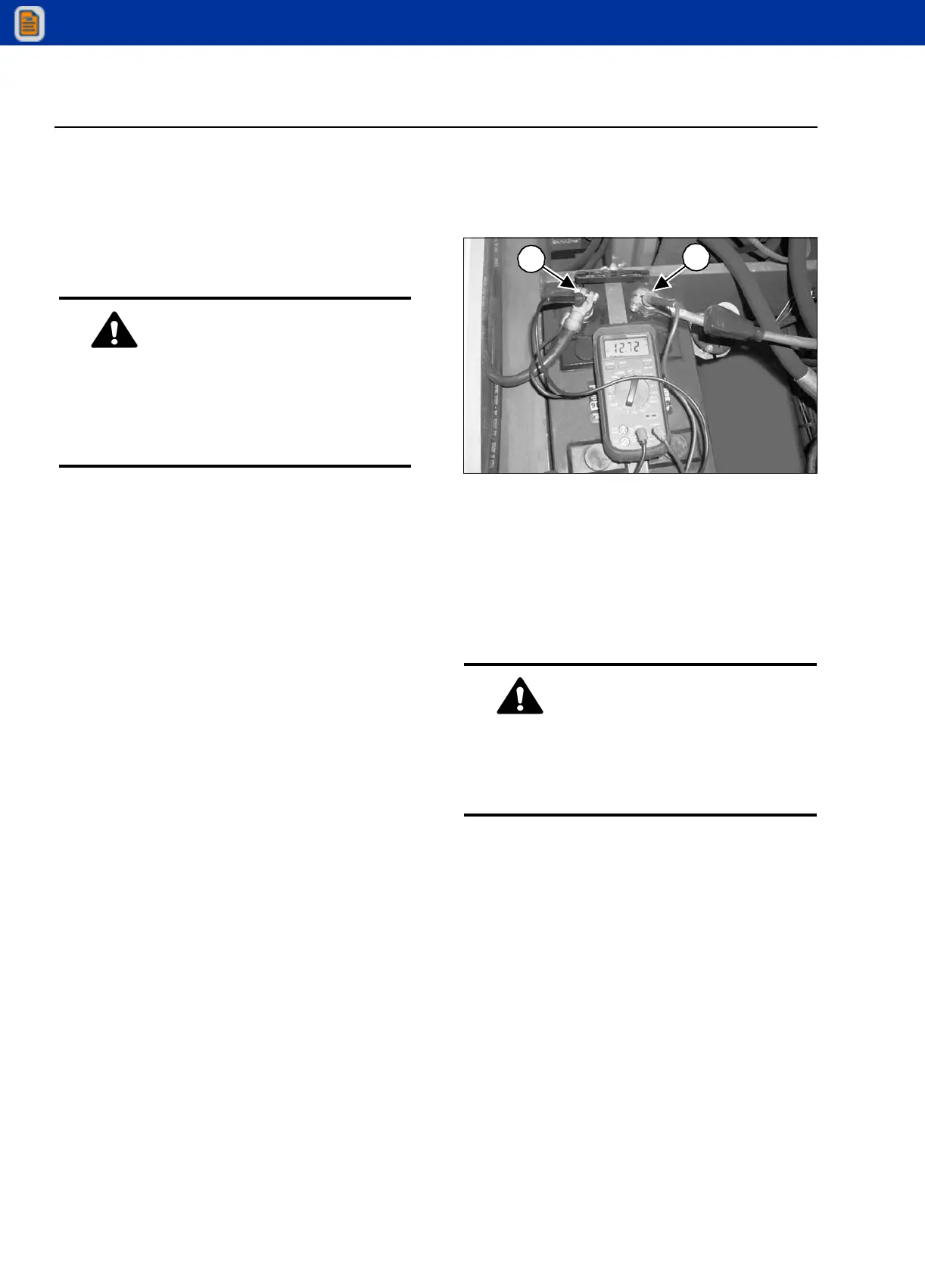
BATTERY TEST
STEP 1
G0805145
Set the multimeter to DC volts. Connect the
multimeter positive (+) test lead to the positive post
(1) and the negative (-) test lead to the negative post
(2) of the battery. The multimeter should read 12 to
13 volts.
If there is no voltage, replace the battery.
If there is voltage but is less than 12 volts proceed to
the next step.
WARNING
When a test involves turning over the engine
or starting the engine, use test leads long
enough to read the multimeter from the
operator’s seat or standing clear of the
machine.
1
2
WARNING
If there is no voltage, the battery has an
internal open circuit. Connecting a charger or
auxiliary battery to a battery with an open
circuit can cause a battery explosion.
RS5-34 Telescopic Handler ELECTRICAL
ELECTRICAL SYSTEM TESTS

 Loading...