Template Date: 1997_02_12
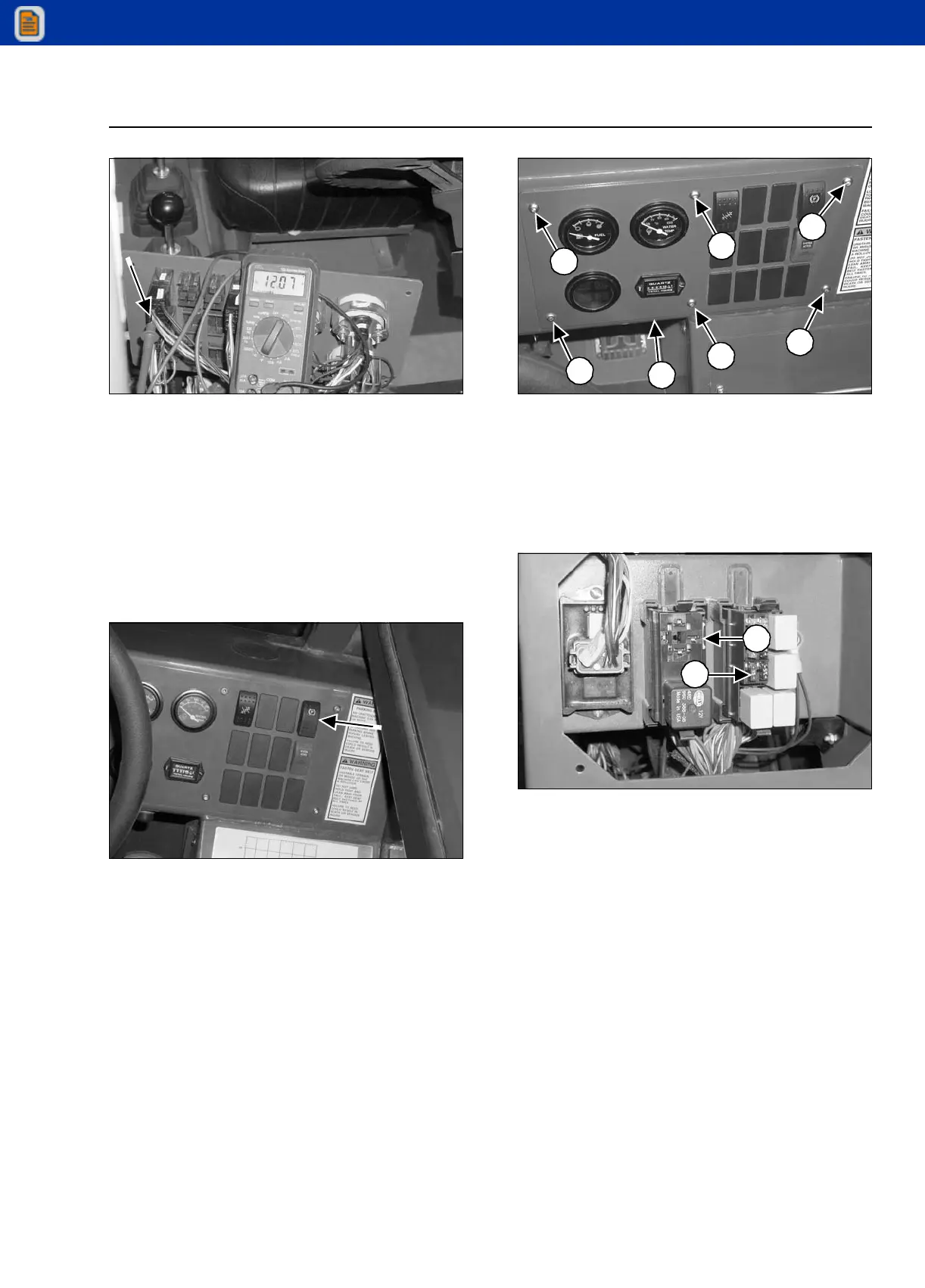
STEP 30
G0805174
Connect the positive (+) test lead to the relay
terminal (tan/red wire) of the park brake switch. With
the key switch and park brake switch in the ON
position, the multimeter should read 12 to 13 volts.
If there is no voltage, replace the park brake switch.
If there is 12 to 13 volts, but no voltage at Step 24,
replace the tan/red wire between the switch and the
relay.
STEP 31
G0805078
Move the park brake switch to the OFF position. The
multimeter should read 0 volts.
If there is 12 to 13 volts, replace the park brake
switch.
STEP 32
G0805182
Install the instrument panel (1) using the six screws
(2).
STEERING MODE CIRCUIT TESTS
STEP 33
G0805166
Check the frame leveling/steer mode fuse (1). Test
for power to the fuse (Step 4) and the ignition relay
(2) (Steps 5 and 6).
1
2
2
2
2
2
2
2
1

 Loading...