16
- For a proper operation of the softener, do not make any extension on
the power supply cable.
- After installation, make sure that the unit does not stand on the power
supply cable.
- Install a filter (6) between the by-pass for the cutting out of the system
and the water inlet of the softener.
- Use flexible hoses or vibration-damping joints for in-out connections
of the softener to the system.
- Connect the drain hose of the valve and the overflow hose of the salt
container to the drain with two separate hoses (supplied with the
system – see installation drawings). IMPORTANT: The drain must be
free (at atmospheric pressure) and not sealed.
- Provide a raceway drain pipe with enough draining capacity.
- The drain must be lower than the
“overflow” level of the tank.
- For pressures below 1.5 atm. a surge
tank shall be installed.
- For pressures above 1.5 atm. a
pressure reducer shall be installed.
- A non-return valve shall be installed after the water meter.
- For potable use a residual water hardness of 15 °f is recommended.
After installation, for start up and testing of the equipment, directly
contact your dealer or installer from whom you have purchased the
machine.
Do not use the equipment before the start up and testing carried out by
your dealer or authorized technical staff.
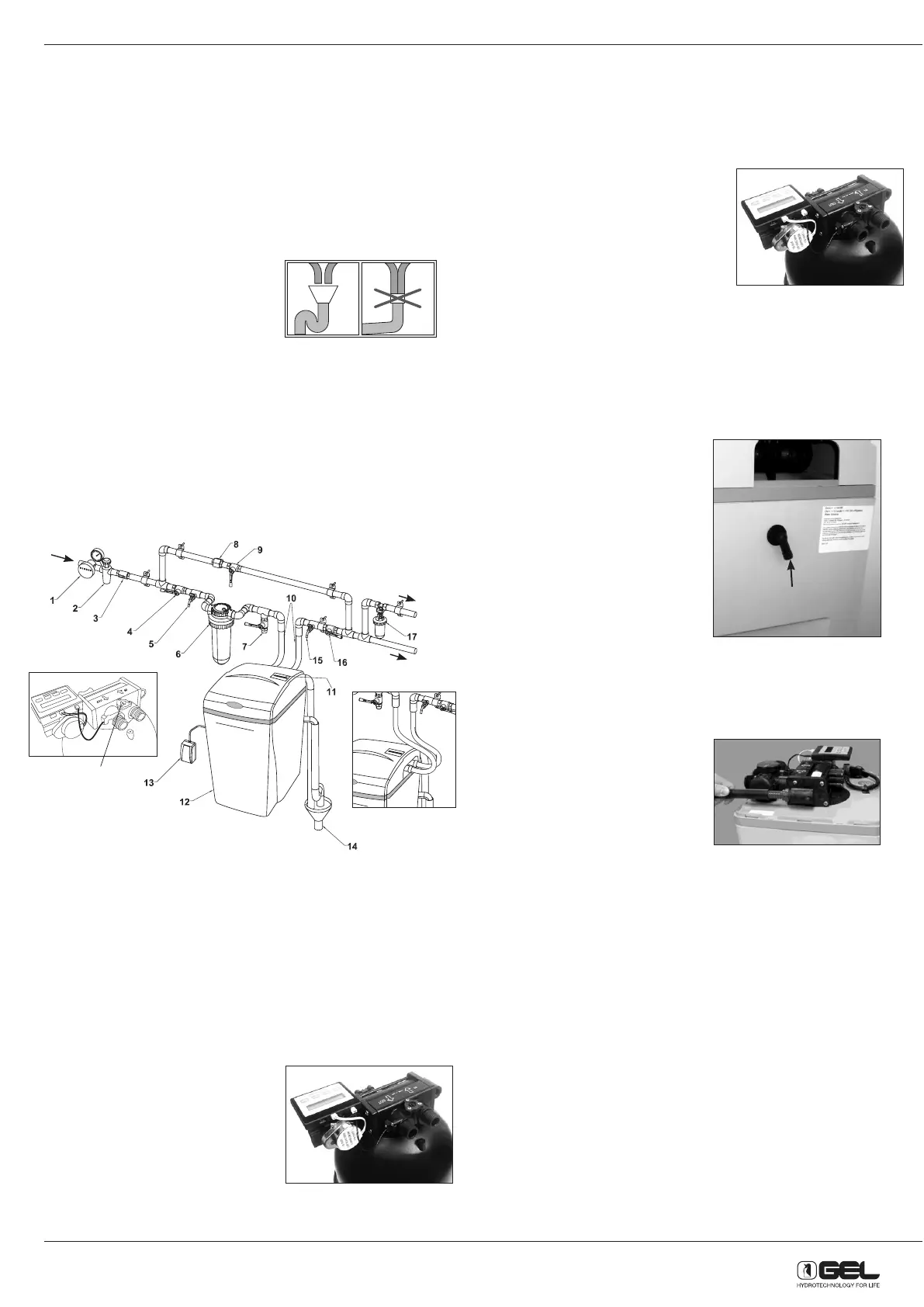
9.2 - INSTALLATION
1) Water meter
2) Pressure reducer (only if necessary)
3) Check valve
4) On-off valve before the system
5) Tap for raw water sample taking
6) Sand filter
7) Filtered water offtake for other uses
8) Pipe union fitting
9) By-pass gate valve
10) Flexible hoses or vibration-damping joints
11) Timer display
12) Brine cabinet
13) Power supply
14) Drains
15) Tap for soft water sample taking
16) On-off valve after the system
17) Anti-scale dosing unit (for boiler protection)
18) Mixing valve
9.3 - INSTALLATION STEPS
9.3.1 Turn off water supply
A. Turn off the water supply.
B. Open the hot and cold water taps to depressurize the lines.
9.3.2 Connect water softener
A. Remove valve cover.
1. Open the salt port lid on the valve cover
and slide it down.
2. Place your fingertips on the bottom,
inner edge of the valve cover (you may
need to use two hands).
3. Squeeze the edge and pull the valve
cover toward yourself until it clicks free
(See Figure 3)
4. Lift and remove the valve cover.
B. Attach the water lines to the appliance in compliance with all state and
local regulations (Figure 1). Do NOT overtighten the connections on
the plastic threads.
C. Check the arrows on the valve to ensure that the water flows in the
proper direction.
9.3.3 Connect overflow connection
The overflow line drains away excess
water, should the tank fill with too much
water or the appliance malfunction.
A. Check that the overflow elbow is in
the down position (Figure 2).
B. Connect with a 1/2-inch I.D. tubing
(size cannot be reduced) the
overflow elbow to a suitable waste
receptor. This tubing is not supplied
with the appliance. Ensure that the
overflow line ends at a drain that is
at least 8 cm lower than the bottom
of the overflow elbow. Maintain a
minimum 5 cm air gap between the
drain line and the flood level rim of
the waste receptor to prevent back-siphoning. The drain line should
be the shortest possible. The overflow connection shall be connected
to a free drain line.
9.3.4 Connect drain line
The drain line carries away the backwash
water produced during the regeneration
cycle.
A. Connect the drain line to the drain
end cap (Figure 3) with a minimum
5/8-inch I.D. tubing (supplied). The
size cannot be reduced.
B. Connect the drain line to a suitable
waste receptor. Maintain a
minimum 5 cm air gap between the drain line and the flood level
rim of the waste receptor to prevent back-siphoning. This drain line
should be the shortest possible.
C. The drain line may be elevated up to 2.4 m from the discharge on the
appliance as long as the water pressure in your system is 2.8 bar or
more.
D. If the drain line is longer than 7.6 m, increase the drain line to 3/4-inch
I.D. The end of the drain line must be equal to or lower in height than
the control valve.
Caution: The drain line must not be kinked, crimped, or restricted in
any way.
9.3.5 Flush Lines
A. Place the appliance in the bypass position (Figure 4).
B. Turn on the water supply valve.
C. Open the nearest cold water faucet to flush the plumbing of any
excess soldering flux, air, or any other foreign material.
SI NO
YES NO
Water
supply
entry
to the boiler
to the system
18
P.S. Inlet connections
in the MINI model are
on a side.
Overflow
elbow
Fig. 2