550_us
34 / 44
Control function
Connectors
24
1 (NC) + -
2 (NO) - +
3 (DA) + +
8 (normally open) + +
+ = available / - = not available
(for connectors 2 / 4 see pictures above)
11.4 Connecting the
control medium
Important:
Assemble the control medium lines
tension-free and without any bends
or knots!
Use appropriate connectors
according to the application.
Thread size for the control medium
connectors 2 and 4:
Actuator size Thread
0M5
1, 2 G 1/8
3, 4, 5 G 1/4
Always make sure you have used the
correct threads. Failure to do so could cause
the control media line to hit someone with
force (due to compressed control medium),
thereby causing death or serious injury.
Function of the actuator would be aff ected
by using incorrect thread size. Incorrect
thread size may change function of process
line [product quality] (or process media could
escape).
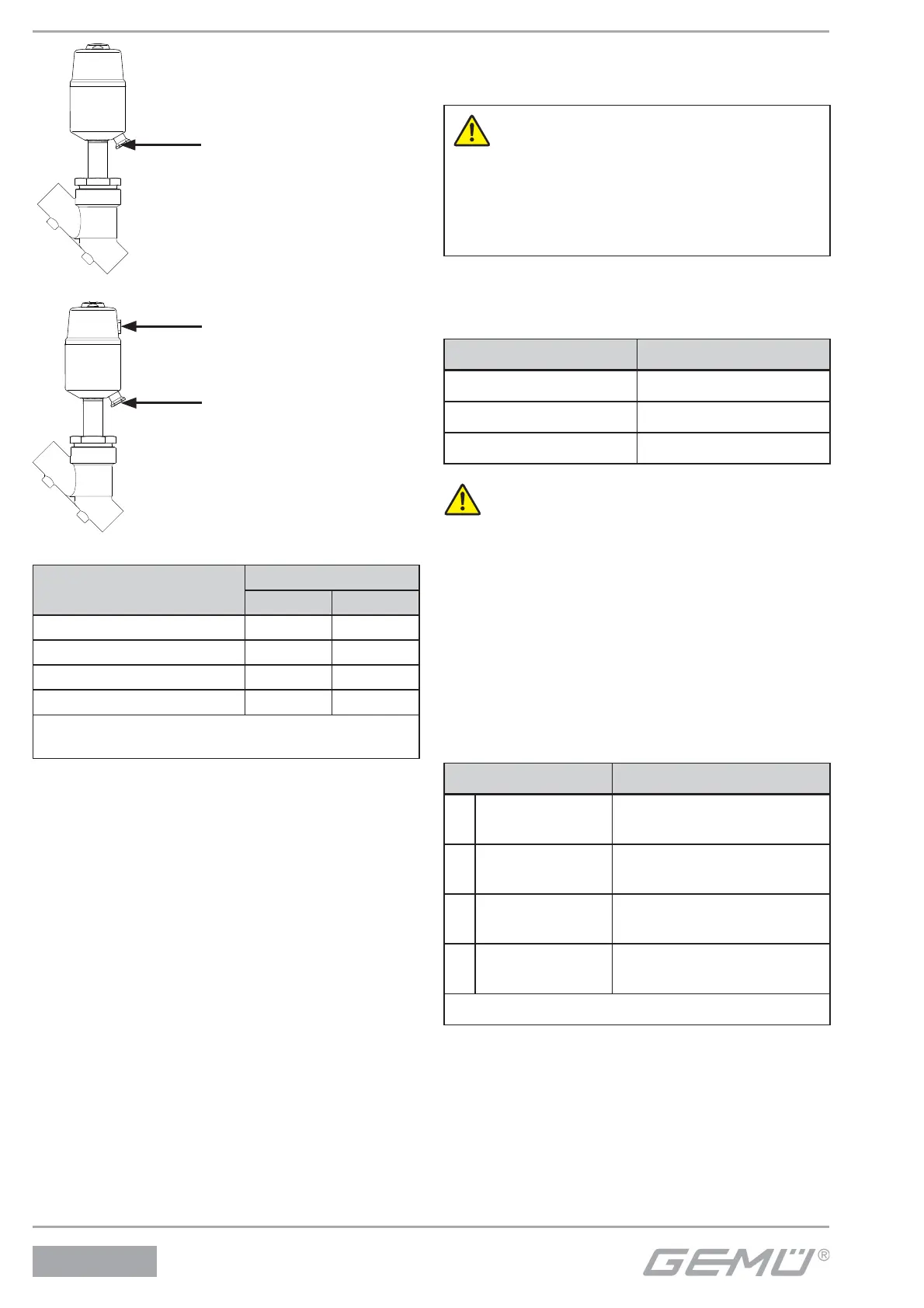
Control function Connector
1
Normally closed
(NC):
2: Control medium (open)
2
Normally open
(NO):
4: Control medium (close)
3
Double acting
(DA):
2: Control medium (open)
4: Control medium (close)
8
Double acting
(normally open)
2: Control medium (open)
4: Control medium (close)
For connectors 2 / 4 see pictures on the left
Connector 2
Connector 4
Connector 2
Control function 1
Control function 2, 3, 8