35 / 44
550_us
12 Assembly / disassembly
of spare parts
See also chapter 11.1 "Assembling the
valve" and chapter 20 "Sectional drawing and
spare parts".
12.1 Disassembly of
actuator and gasket 4
1. Move actuator A to the open position.
2. Loosen union nut a.
3. Remove actuator A from valve body 1.
4. Remove gasket 4.
5. Move actuator A to the closed position.
+
Important:
After disassembly, clean all parts
of contamination (do not damage
parts). Check parts for potential
damage, replace if necessary (only
use genuine parts from GEMÜ).
12.2 Replacement of seat seal
1. Disassemble actuator A as described in
chapter 12.1, items 1-4.
2. Move actuator A to the open position.
3. Loosen nut d on spindle b (hold spindle
b with appropriate tool that will not
damage the spindle surfaces). Remove
washer e and seat seal 14.
4. Clean all parts, do not scratch or damage
the parts during cleaning.
5. Insert new seat seal 14.
6. Insert washer e.
7. Apply appropriate mounting glue on the
thread of spindle b.
8. Move actuator A to the open position.
9. Fix with nut d (hold spindle b with
appropriate tool that will not damage the
spindle surfaces).
10. Assemble actuator A as described in
chapter 12.3, items 1-5.
12.3 Assembly of actuator
and gasket 4
1. Move actuator A to the open position.
2. Insert new gasket 4 in valve body 1.
3. Actuator rotatable 360°. Position of the
control medium connectors is optional.
4. Place actuator A on valve body 1
approx. 90° anticlockwise to the desired
end position of the control medium
connectors and screw it down hand tight
using union nut a.
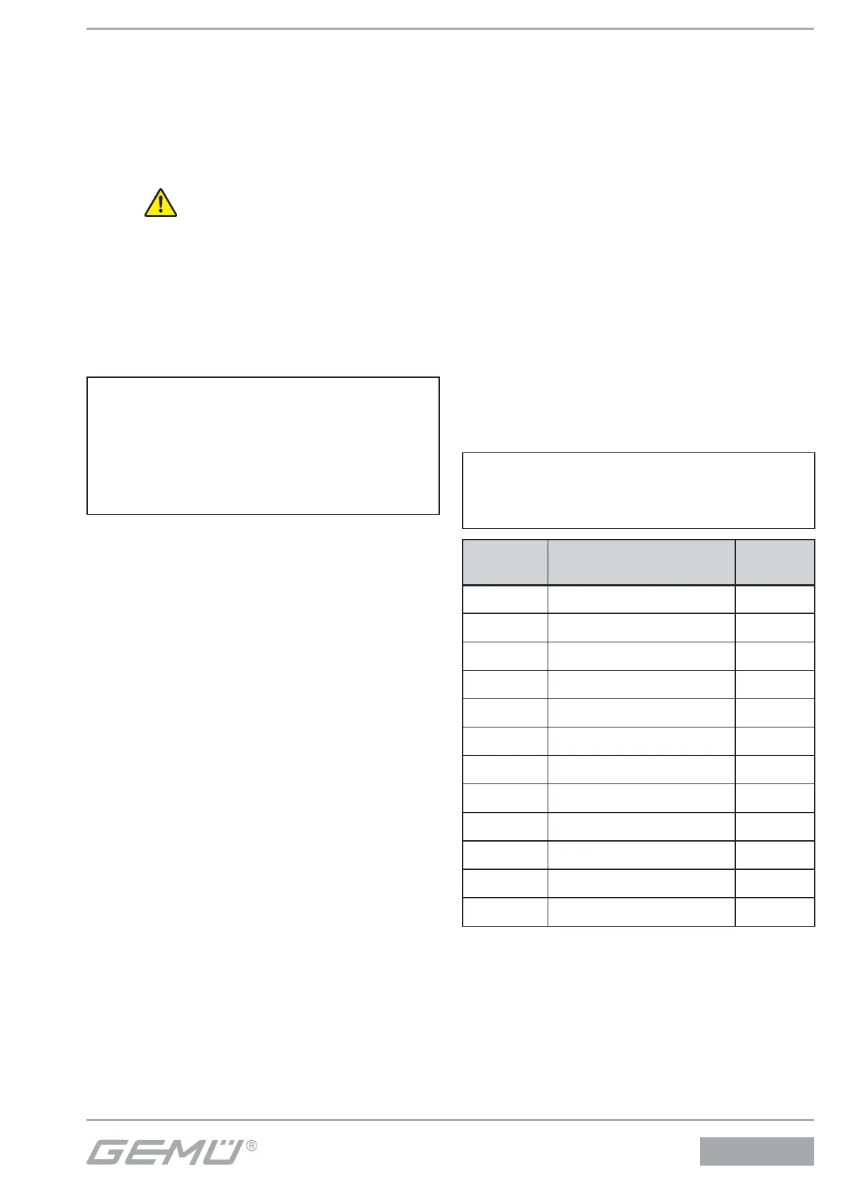
5. Tightening the union nut a with an open-
end wrench (torques see table on next
page) rotates the actuator clockwise
approx. 90° to the desired position.
6. Move actuator A to the closed position,
check function and tightness of
completely assembled valve.
+
Important:
Replace gasket 4 during every
actuator disassembly / assembly.
Nominal
size
Actuator size
Torques
[Nm]
DN 8 0G / 0M 35
DN 10 0G / 0M 35
DN 15 0G / 0M 35
DN 10 1G / 1M 90
DN 15 1G / 1M / 2G / 2M 90
DN 20 1G / 1M / 2G / 2M / 3G / 3M 100
DN 25 2G / 2M / 3G / 3M / 4G 120
DN 32 2G / 3G / 3M / 4G / 5G 120
DN 40 3G / 3M / 4G / 5G 150
DN 50 3G / 3M / 4G / 5G 200
DN 65 5G 260
DN 80 5G 280